PROJECT TITLE    NICMOS                                                                             
SUBJECT TITLE    SI Command Blocks and Flow Charts                                                  
PREPARED BY                 PHONE NO.                APPROVED BY                        DATE          
G. Blue                     (303) 939-6930           J. Troeltzsch                                    
SCOPE/TEXT:                                                                                          
   This SER is being used as a tool for collecting the information needed for the generation of      
   commands for the NICMOS  Science Instrument (SI). This information is formally provided in the    
   DM-05 document.  This is revision F which incorporates the red lines and comments to the          
   revision E version as well as the most current design information.   This SER contains the        
   information listed below.  1) NICMOS Commanding Requirements 1.1) System Level Command            
   Requirements 1.2) NICMOS Command Terms and Definitions  2) DM-05 Place Holder  3) SI Level        
   Modes Definition 3.1) Mode Definitions and Flow Diagram 3.2) Hardware States 3.3) Mode            
   Transition Table 3.4) NICMOS Component States Information.  4) Operations Description Timing      
   and Constraints 4.1) NSSC-I Timing Data 4.2) NICMOS Timing Data  5) Macro Activation Request      
   Definitions  6) Parameter Definitions 6.1 Mechanism Limits and Settings 6.2 Symbols of Interest   
   6.2.1 NICMOS Address 6.2.2 NICMOS Enumeration Literals 6.2.3 NSSC-I Address 6.2.4 NSSC-I          
   Offsets 6.2.5 NICMOS Offsets 6.3 Filter Wheel Proposal Parameter Definitions  7) NICMOS Reset     
   Conditions 7.1 Hardware Resets 7.2 Software Resets                                                
DISTRIBUTION:                                                                                       
   Ball Software                          STScI W. Baggett    GSFC J. Lawson A.   U of A G.Schneider  
   Group Operations                       V. Balzano D.       Rankin H. Thomas                        
   Group                                  Chance T Wheeler    L. Olson                                

1.0 NICMOS COMMANDING REQUIREMENTS

1.1 System Level Command Requirements

The following table defines the top level NICMOS requirements which affect the generation of command blocks, macros, and PSTOL procedures. The requirements listed in the first column were extracted from the document shown in the second column. The plain text in the table represents the exact wording from the document. Our additions and deletions are shown in italics and strikeouts.

The CEI Spec identified in the right hand column is the Part II revision A version dated 18 October 1994.

NICMOS Commanding Requirement                                      Traceability                
Operation of the cameras will include: * controlling the FPAs      CEI Spec. 3.1.2 NICMOS      
for data acquisition via interpretation and implementation of      General Description         
uplinked macro commands; * commanding mechanisms to select                                     
filter wheel positions; * commanding mechanisms to provide field                               
offsets to allow background subtraction; * commanding mechanisms                               
to provide on-orbit optical alignment of pupil shear and focus;                                
* commanding flat-field illumination lamps.                                                    
The NICMOS shall interact with the SI C&DH in a manner similar     CEI Spec. 3.2.1.1           
to the first generation instruments, with the added capability     Operations                  
of being operated utilizing macro commands uplinked to the                                     
NICMOS Control Section.  NICMOS will have a minimum of five                                    
operational states: Operate, Hold, Safe, Boot/Suspend, and                                     
Observe. The NICMOS operations shall be commanded via RIU                                      
commands transmitted over the Supervisory Bus (CEI-P1:                                         
3.2.1.1.4.1).  The Operate state is a transitional state in                                    
which the NICMOS instrument is readied for activation of the                                   
observe state or for returning to hold after termination of an                                 
observe state. The major functional capabilities within the                                    
Observe state shall be: offsetting the field of view pointing,                                 
coronographic target acquisition, science/engineering data                                     
acquisition (imaging), and flat-field illumination. (CEI-P1:                                   
3.2.1.1.5) Field of view pointing offsets will utilize the Small                               
Angle Maneuvering system (SAMS) of the HST or the Field Offset                                 
Mechanism (FOM) in NICMOS. Target acquisition will utilize the                                 
HST SAMS.                                                                                      

NICMOS Commanding Requirement                                      Traceability                
The three cameras shall be capable of independent operation        CEI Spec. 3.2.1.1           
(CEI-P1: 3.1.1). The main concept of independent operation is      Operations                  
the ability to schedule each NICMOS camera operation without                                   
concern about the operational state of the other cameras. This                                 
pertains to positioning of the filter wheels, initiating and                                   
terminating integrations, performing the various readout mode of                               
the detectors, and storage of the resultant data, The operations                               
are not independent for movement of the FOM or for small angle                                 
maneuvers by HST. The independence of filter wheel operation is                                
a goal, but may be compromised by insufficient noise immunity                                  
motor commanding during movement of the filter wheels. Also,                                   
concurrent read out of the independent detectors must be                                       
synchronized to achieve adequate noise immunity. Hence, the                                    
integration start times may be dependent to within the pixel                                   
access time, that is, the start time may be advanced or delayed                                
by the pixel access time in order to achieve synchronization.                                  
In the Hold state, engineering data from key health and status                                 
sensors shall be acquired through the RIU via the                                              
supervisory/reply bus. In addition, the RIU shall be used to                                   
transfer discrete commands to control power within the                                         
instrument for heaters, TECs, pressure transducer, and turning                                 
on/off the power to the Main Electronics Box (MEB), which                                      
contains the Control Section (CS). In the Hold state, the filter                               
wheels shall be in the opaque blank position, and the FOM shall                                
be in the MIQ position.  In the Safe state, only power to the                                  
TECs, LVPS hold converter, pressure transducer, and heaters will                               
be maintained, Recovery from Safe state shall consist of                                       
returning NICMOS to the Hold state (CEI-P1: 3.2.1.1.9).                                        
HST acquisition pointing shall be used to place the desired        CEI Spec. 3.2.1.1.1         
target at specified position within the FOV of the desired         Target Acquisition          
camera with the FOM mirror in the MIQ position (CEI-P1:                                        
3.2.1.1.5.1.1).                                                                                
An observation is defined to be a set of NICMOS actions that       CEI Spec. 3.2.1.1.2 Data    
result in production of output data from a camera (CEI-P1:         Acquisition                 
3.2.1.1.5).  An observation may contain multiple integrations of                               
the FPA.  The Filter Wheel(s) may be changed between                                           
integrations. The FOM shall not be moved during an integration                                 
(CEI-P1: 3.2.1.1.5). Each of the NICMOS cameras shall be capable                               
of integration times from 0.2 to 10,000 seconds (CEI-P1:                                       
3.2.1.1.5.2).  The detector control shall be able to make                                      
multiple non-destructive reads during an integration (CEI P1:                                  
3.2.1.1.7).  In addition, the NICMOS camera shall be capable of                                
integration times as short as 0.001 seconds per pixel (CEI-P1:                                 
3.2.1.1.5.2). The NICMOS operation shall be capable of                                         
performing simultaneous or overlapping integration of the three                                
cameras with different integration times for each camera                                       
(CEI-P1: 3.2.1.1.5).                                                                           

NICMOS Commanding Requirement                                      Traceability                
On-orbit installation and checkout of NICMOS shall be designed     CEI Spec. 3.2.1.1.3         
and configured to be brought to a thermally safe state with a      On-Orbit Installation &     
minimum of commands following electrical connection to the HST.    Checkout                    
Capability to perform a standard functional test shall be                                      
available to verify basic NICMOS science operation. The nominal                                
elapsed time for running this test will be two hours or less.                                  
This test will be performed between the NICMOS installation EVA                                
and the next scheduled EVA.                                                                    
NICMOS alignment will be performed by a sequence of ground         CEI Spec. 3.2.1.1.4         
initiated commands to the PAM which will adjust the focus,         On-Orbit Alignment &        
position (+/- 5mm), and direction of the chief ray x-tilt (+/-     Calibration                 
10 arc minutes), and y-tilt (+/- 10 arc minutes). Analysis of                                  
images obtained at the PAM settings, performed on the ground,                                  
will determine the necessary commands to set the PAM for optimum                               
image quality.  Commands for maintenance and diagnostics                                       
functions shall be included. (CEI-P1: 3.2.1.1.4.1)                                             
Commands shall initiate analysis, formatting routines, data        CEI Spec. 3.2.1.6           
acquisition, and transmission of science data and engineering      Commands and Data Handling  
data.  NICMOS shall have the capability to store data internally                               
in a buffer memory. The buffer memory size will accommodate at                                 
least 85 images. NICMOS shall be able to transmit data to the                                  
NSSC-I and/or SDF while new data are being collected.                                          
The NICMOS shall have the capability to perform diagnostic tests   CEI Spec. 3.5.1.3 Checkout  
upon command. These tests shall include, but not be limited to,                                
I/O channel and memory test for each internal processor and                                    
operational tests of each mechanism Diagnostic test procedures                                 
using these capabilities shall be developed for ground                                         
operational checkouts and for use in flight to verify continued                                
health of the instrument (CEI-P1: 3.5.1.2)                                                     

1.2 NICMOS Command Terms and Definitions

HST 48 bit forward link commands with a 6 bit OP Code of 010 000, and a 5 bit RIU address of 10 100, result in serial digital and discrete commands sent to the NICMOS SI via the normal command path within the HST.

HST 48 bit forward link commands with a 6 bit OP Code of 100 111 or 100 011, and a 5 bit RIU address of 10100, result in serial digital and discrete commands sent to the NICMOS SI via the backup command path within the HST. The format differences between the normal path commands and the alternate path commands are transparent to the NICMOS CS flight software (CS FSW).

Regardless of the command path used, discrete commands are routed directly to the selected NICMOS hardware by the RIU. The serial digital commands (16 bits) are interpreted by the NICMOS CS flight software as; Normal Macro Activation Requests, Immediate Macro Activation Requests, or Parameter Data. Within the flight software, Immediate Macro Activation Requests have priority over Normal Macro Activation Requests. Parameter data is the data associated with Normal Macro Activation Requests. Immediate Macro Activation Requests can not include Parameter Data.

There are two types of Macros: Code-Level Macros and High Level Macros. Code Level Macros relate directly to an instrument function implemented by the NICMOS flight software. High level macros relate to an ordered list of Code-Level Macros (or other High Level Macros) required to perform some "higher level" SI function. An example of a High Level Macro is Non-Prime Parallel Observe which is implemented by executing several Code Level Macros.

Stored commands are commands which are executed onboard the HST by the NSSC-I computer.

Stored commands are either Relative Time Code Sequence (RTCS) relative commands or Absolute Time commands (ATC).

A Command Block is a group of RTCS or Absolute Time commands which have been predefined in the Project Data Base (PDB) to perform a specific function.

Macro activation requests are sent from the ground as NSSC-I memory uploads in the form of Command tables. The table data is converted by the Macro AP software into RTCS commands. The Macro AP then marks the RTCS for execution by the NSSC-I command processor.

There are five separate NSSC-I memory areas used for table uploads, three are reserved for detector specific stored commanding (one for each of the detectors), and two non-detector specific command memory buffers (one for real-time commanding, and one for stored commands). The table data is defined in the Table Format Parameter File which is provided in section 9.

3.0 SI LEVEL MODES DEFINITION

3.1 Mode Definitions and Flow Diagram

Figure 3.1-1 shows the modes defined for NICMOS and the command groups which facilitate the transitions between the modes. Those command groups shown in the figure which do not originate from a specific mode, can be called from any higher level mode.

Figure 3.1-1 NICMOS modes and mode transition command groups

NICMOS Mode Definitions

Mode: OFF

Description: This non-orbit configuration is used during testing and storage of the science instrument. In general, all NICMOS relays will be open, the TEC, pressure transducer, and buffer box power will be set to side 2, and the non-redundant sensors set to side 1.

Mode: LAUNCH CONFIGURATION

Description: This configuration covers the time period from the last dewar servicing on the ground until installation into HST by the shuttle astronauts. When the instrument is in this mode, specific relays have been configured for on-orbit installation into the HST. While on the ground, the SI is powered on only to pre-configure the relays and then power is removed until the SAFE mode is entered.

Mode: SAFE

Description: This on-orbit configuration is used to; (1) place the instrument into a thermal safe state using a minimum amount of commands following electrical connection to the HST, or (2) to place the instrument into a thermal safe state following an instrument or spacecraft anomaly.

The SAFE mode configuration includes the relay settings defined in the LAUNCH CONFIGURATION mode and closing the four HST PDU relays to provide power to NICMOS. In this mode, the NSSC-I can be on or off.

Recovery from the SAFE mode consists of transitioning to the HOLD mode.

Mode: HOLD

Description: Hold is a routine on-orbit configuration state for the NICMOS instrument. This mode will be entered when the science instrument is not scheduled for operations. The HOLD mode contains all the settings of the SAFE mode with NICMOS safing protection enabled using the NSSC-I computer. Safing protection is limited to NSSC-I limit checking of the NICMOS HOLD mode telemetry data.

Mode: BOOT

Description: This on-orbit configuration has two purposes; (1) transition the instrument from HOLD to OPERATE, and (2) to assist in fault isolation.

When the BOOT mode is entered from the HOLD mode, the science instrument is being made ready for operations. See the mode transition table in this section for a summary of the actions taken.

Fault isolation is supported by activation of the BOOT mode via the NSUSPND (suspend) command sequence. From any higher mode, the NSUSPND sequence will halt the NICMOS CS software running in EDAC RAM and begin execution of the boot software in PROM. At this point, a subset of the normal NICMOS commands can be used which includes dumping the contents of EDAC RAM to the ground for error detection and evaluation.

The NSUSPND command sequence will also set the Buffer Boxes to the "off" side, and reset the DES and SES effectively turning off the detectors, mechanisms and calibration lamps.

Mode: OPERATE

Description: This mode is used to either (1) configure the instrument for observations, or (2) provide an ordered termination from the OBSERVE mode. For SI configuration, the three buffer boxes will be activated and the DES will be initialized. A one hour warm-up time is required prior to transitioning to the OBSERVE mode to allow the DES electronics to stabilize. When the OPERATE mode is entered from the OBSERVE mode, the SI will be placed in a known state. This includes repositioning the filter wheels to a blank filter.

In the OPERATE mode the flight software is in its full-up configuration.

Mode: OBSERVE

Description: NICMOS will be placed in the OBSERVE mode during all camera exposures. Repositioning back to the OPERATE mode is not required for multiple images. OBSERVE mode operations are divided into the detector modes which are defined in section 4.

3.2 HARDWARE STATES

Within the OPERATE and OBSERVE Modes, the PAM and Calibration Lamps will be configured into unique 'States'. These States are shown in Figure 3.2-1.

Figure 3.2-1 PAM & Calibration Lamp State transitions

Mode: PAM HOLD

Description: In this state, power to the PAM sensors is off. Power to the PAM motors is on whenever the Operate relay is closed. The PAM sensors include an LVDT focus sensor and DITS tilt sensors. The DITS sensor requires a 1 hour warm-up period prior to use.

PAM Warm-up Time: 1 hour

Mode: PAM ON

Description: Power is available at the PAM sensors. The NEPAMSEN command is used to enable power and the NDPAMSEN command is used to disable power to the sensors.

PAM Supression Time: 8 hours

Mode: LAMP OFF

Description: NICMOS has six calibration lamps with three lamps per instrument side. In the LAMP OFF state all lamps are off. The Calibration Lamps are managed to minimize the number of on/off cycles.

Lamp Warm-up Time: 1 second

Mode: LAMP ON

Description: In the LAMP ON state one (or more) of the lamps are illuminated. It is possible to activate more than one lamp at a time (non-standard operations), see the Calibration Lamp macro definition in section 5.70 for more information.

Lamp Supression Time: TBD

3.3 Mode Transition Table

Current  Next       Transition                                 Action                               
 Mode    Mode         Event                                                                         
Off      SAFE     ground test     * provide power to NICMOS RIU-A and RIU-B from the PDU   IF       
                  or SI           side 1 selected: * set RIU-A to stand-by 2 & RIU-B to stand-by    
                  operation       1 * configure the ground for RIU-A operations * verify that       
                  activation      RIU-A is outputting conditioned analog telemetry: + perform       
                  sequence        manual verification of the RIU temperature telemetry data +       
                  --------------  check RIU status and output status message * configure NICMOS     
                  ------- Check   for SAFE Mode on side 1 (ZNLCSAF1): + disable side 1 & 2          
                  Dates:  PSTOL   Operate power relays + disable side 2 Hold relay + enable side    
                  _5/15/95_       1 Hold relay + disable side 2 Thermal Controller power relays +   
                  Instruct        enable side 1 Thermal Controller power relay  + set the TEC       
                  ___n/a___       power side select relay to side 1 + enable TEC Inner V2 & V3      
                                  power relays + enable TEC Outer power relay + disable PAM         
                                  sensors + set the Pressure Transducer power side select relay     
                                  to side 1 + set all six (6) buffer box side select relays to      
                                  side 2 + set the non-redundant sensor telemetry routing relays    
                                  to side 1 (NSIDEON) * verify the relay settings in telemetry &    
                                  display errors  ELSE (side 2 selected as primary) * set RIU-B     
                                  to stand-by 2 & RIU-A to stand-by 1 * configure the ground for    
                                  RIU-B operations * verify that RIU-B is outputting conditioned    
                                  analog telemetry: + check RIU power status and output status      
                                  message * configure NICMOS for SAFE Mode on side 2 (ZNLCSAF2):    
                                  + disable side 1 & 2 Operate power relays + disable side 1 Hold   
                                  relay + enable side 2 Hold relay + disable side 1 Thermal         
                                  Controller power relays + enable side 2 Thermal Controller        
                                  power relay  + set the TEC power side select relay to side 2 +    
                                  enable TEC Inner V2 & V3 power relays + enable TEC Outer power    
                                  relay + disable PAM sensors + set the Pressure Transducer power   
                                  side select relay to side 2 + set all six (6) buffer box side     
                                  select relays to side 1 + set the non-redundant sensor            
                                  telemetry routing relays to side 2 (NSIDEON) * verify the relay   
                                  settings in telemetry & display errors ENDIF  IF SDF selection    
                                  = Primary * enable the primary SDF interface (path A) ELSE *      
                                  enable the secondary  SDF interface (path B) ENDIF  * operator    
                                  verification - GO for Power-Up? * provide power to NICMOS side    
                                  1 & 2 * enable PORTS limits checking                              

SI Level Mode Transition Table cont.

Current  Next       Transition                                 Action                               
 Mode    Mode         Event                                                                         
SAFE     OFF      ground test     * disable power to NICMOS side 1 & 2 (CFOSPF & CFOSRF)  *         
                  termination     configure NICMOS for OFF Mode (ZNOFF): + disable side 1 & 2       
                  sequence        Hold power relays + disable side 1 & 2 Operate power relays +     
                  --------------  disable side 1 & 2 Thermal Controller power relays + set the      
                  ------- Check   TEC power side select relay to side 2 + disable TEC Inner V2 &    
                  Dates:  PSTOL   V3 power relays + disable TEC Outer power relay + disable PAM     
                  _8/4/95_        sensors + set the Pressure Transducer power side select relay     
                  Instruct        to side 2 + set the non-redundant sensor telemetry routing        
                  ___n/a___       relays to side 2 (NSIDEOFF) + set all six (6) buffer box side     
                                  select relays to side 2 + enable the primary SDF interface        
                                  (path A) * verify the relay settings in telemetry & display       
                                  errors (needs to be added) * disable PORTS limit checking         
                                  (needs to be added) * disable power to RIU-A & RIU-B              
         Launch   launch minus    * mode transition prerequisite: + camera 1 filter wheel set to    
         Config-  TBD (the last   TBD position + camera 2 filter wheel  set to TBD position +       
         uration  dewar           camera 3 filter wheel  set to TBD position  * disable power to    
                  servicing)      NICMOS side 1 & 2 * configure NICMOS for SAFE Mode on side 1      
                  --------------  (ZNLCSAF1): + disable side 1 & 2 Operate power relays + disable   
                  ------- Check   side 2 Hold relay + enable side 1 Hold relay + disable side 2     
                  Dates:  PSTOL   Thermal Controller power relays + enable side 1 Thermal           
                  _               Controller power relay  + set the TEC power side select relay     
                  _  Instruct     to side 1 + enable TEC Inner V2 & V3 power relays + enable TEC    
                  ___n/a___       Outer power relay + disable PAM sensors + set the Pressure        
                                  Transducer power side select relay to side 1 + set all six (6)    
                                  buffer box side select relays to side 2 + set the non-redundant   
                                  sensor telemetry routing relays to side 1 (NSIDEON) * verify      
                                  the relay settings in telemetry & display errors  * configure     
                                  the NICMOS RIUs: + set RIU-B to stand-by 2 + set RIU-A to         
                                  stand-by 1  * disable power to RIU-A & RIU-B                      

SI Level Mode Transition Table cont.
Current  Next       Transition                                 Action                               
 Mode    Mode         Event                                                                         
Launch   Safe     NICMOS has      * provide power to NICMOS RIU-A and RIU-B from the PDU   IF       
Config-           been            side 1 selected for operations * configure the RIUs: + set        
uration           installed in    RIU-B to stand-by 2  &  RIU-A to OFF * verify the RIU status &    
                  the HST and     display errors * configure the RIUs: + set RIU-A to stand-by 2    
                  the ground      &  RIU-B to stand-by 1 * verify the RIU status & display errors   
                  has received    * configure NICMOS for SAFE Mode on side 1 (ZNLCSAF1): +          
                  the go-ahead    disable side 1 & 2 Operate power relays + disable side 2 Hold     
                  for the         relay + enable side 1 Hold relay + disable side 2 Thermal         
                  NICMOS          Controller power relay + enable side 1 Thermal Controller power   
                  aliveness       relay  + set the TEC power side select relay to side 1 + enable   
                  test            TEC Inner V2 & V3 power relays + enable TEC Outer power relay +   
                  --------------  disable PAM sensors + set the Pressure Transducer power side      
                  ------- Check   select relay to side 1 + set all six (6) buffer box side select   
                  Dates:  PSTOL   relays to side 2 + set the non-redundant sensor telemetry         
                  _               routing relays to side 1 (NSIDEON) * verify the SI                
                  _  Instruct     configuration & display errors  ELSE side 2 selected for          
                  ___n/a___       operations * configure the RIUs: + set RIU-A to stand-by 2  &     
                                  RIU-B to OFF * verify the RIU status & display errors *           
                                  configure the RIUs: + set RIU-B to stand-by 2  &  RIU-A to        
                                  stand-by 1 * verify the RIU status & display errors  *            
                                  configure NICMOS for SAFE Mode on side 2 (ZNLCSAF2): + disable    
                                  side 1 & 2 Operate power relays + disable side 1 Hold relay +     
                                  enable side 2 Hold relay + disable side 1 Thermal Controller      
                                  power relay + enable side 2 Thermal Controller power relay  +     
                                  set the TEC power side select relay to side 2 + enable TEC        
                                  Inner V2 & V3 power relays + enable TEC Outer power relay +       
                                  disable PAM sensors + set the Pressure Transducer power side      
                                  select relay to side 2 + set all six (6) buffer box side select   
                                  relays to side 1 + set the non-redundant sensor telemetry         
                                  routing relays to side 2 (NSIDEON) * verify the SI                
                                  configuration & display errors ENDIF  * apply power to NICMOS     
                                  side 1 & 2  from the PDU                                          

SI Level Mode Transition Table cont.

Current  Next       Transition                                 Action                               
 Mode    Mode         Event                                                                         
Safe     Hold     normal          * Inhibit all NICMOS AP's * Halt & inhibit NICMOS unique RTCS's   
                  activation or   * Halt & inhibit NICMOS suspend RTCS * Inhibit NICMOS safing      
                  SAFE mode       RTCS * Clear NICMOS sequence request bits (pending rtcs           
                  recovery        requests) * Set NICMOS safing flag to the 'recover' value *       
                  sequence        Load & activate the SAFE to HOLD RTCS  * Configure the RIUs: +    
                  --------------  Set active RIU to Stand-by 2 + Set other RIU to Stand-by 1 *      
                  ------- Check   configure NICMOS for HOLD mode on the selected side:   (for       
                  Dates:  PSTOL   PSTOL, use the ZNLCSAF1 -or- ZNLCSAF2 cmd group) + Disable the    
                  _8/4/95_        Operate relay (both sides) + Disable the Hold relay on the off    
                  Instruct        side + Enable the Hold relay on the on side + Disable Thermal     
                  __5/4/95_       Controller power relay on the off side + Enable Thermal           
                                  Controller power relay on the on side + Enable TEC side select    
                                  power to the on side + Enable TEC Inner V2 and V3 power relays    
                                  + Enable TEC Outer power relay + Disable PAM sensors (DITS &      
                                  LVDT) power relay + Pressure Transducer power to the on side +    
                                  Set buffer boxes to the off side  * Enable the NICMOS NSSC-I      
                                  safing FSW (AP-23) * Clear the NSSC-I Suspend flag * Clear the    
                                  NSSC-I Checksum flag * Load the SDF formats                       

SI Level Mode Transition Table cont.

Current  Next       Transition                                 Action                               
 Mode    Mode         Event                                                                         
SAFE     SAFE     Side switch     IF current side = 1 * Configure the RIUs for operations on side   
                  --------------  2: + configure the ground for RIU B operations + Set RIU B to     
                  ------- Check   Stand-by 2 + Set RIU A to Stand-by 1  * configure NICMOS for      
                  Dates:  PSTOL   SAFE Mode on side 2 (ZNLCSAF2): + disable side 1 & 2 Operate      
                  ________        power relays + disable side 1 Hold relay + enable side 2 Hold     
                  Instruct        relay + disable side 1 Thermal Controller power relay + enable    
                  ________        side 2 Thermal Controller power relay  + set the TEC power side   
                                  select relay to side 2 + enable TEC Inner V2 & V3 power relays    
                                  + enable TEC Outer power relay + disable PAM sensors + set the    
                                  Pressure Transducer power side select relay to side 2 + set all   
                                  six (6) buffer box side select relays to side 1 + set the         
                                  non-redundant sensor telemetry routing relays to side 2           
                                  (NSIDEON) * verify the SI configuration & display errors  ELSE    
                                  configure for operations on side 1: * Configure the RIUs for      
                                  side 1: + configure the ground for RIU A operations + Set RIU A   
                                  to Stand-by 2 + Set RIU B to Stand-by 1  * configure NICMOS for   
                                  SAFE Mode on side 1 (ZNLCSAF1): + disable side 1 & 2 Operate      
                                  power relays + disable side 2 Hold relay + enable side 1 Hold     
                                  relay + disable side 2 Thermal Controller power relay + enable    
                                  side 1 Thermal Controller power relay  + set the TEC power side   
                                  select relay to side 1 + enable TEC Inner V2 & V3 power relays    
                                  + enable TEC Outer power relay + disable PAM sensors + set the    
                                  Pressure Transducer power side select relay to side 1 + set all   
                                  six (6) buffer box side select relays to side 2 + set the         
                                  non-redundant sensor telemetry routing relays to side 1           
                                  (NSIDEON) * verify the SI configuration & display errors ENDIF    

SI Level Mode Transition Table cont.

Current  Next       Transition                                 Action                               
 Mode    Mode         Event                                                                         
Hold     Boot     normal          * Initialize NSSC-I flight software + Enable suspend & unique     
                  activation      RTCS sequences + Enable NFMACRO (AP-22) for execution  (with      
                  sequence        init) + Enable NFCSCOMM (AP-21) for execution (with init) *       
                  --------------  Disable Operate relay on the off side * Enable Operate relay on   
                  ------- Check   the on side   (Just prior to the major frame for TLM sync) *      
                  Dates:  PSTOL   Initialize the NICMOS BOOT software: + Disable bus wait state +   
                  _8/4/95_        Enable watchdog timer + Enable EDAC detection + Enable reset on   
                  Instruct        multi-bit errors + Enable auto correction of single bit errors    
                  __5/4/95_       + Enable software refresh of EDAC RAM + Enable A/D collection +   
                                  Patch limit check values in EDAC if necessary + Turn on CS        
                                  limit checking + Enable science data interface  Note: PSTOL       
                                  procedure NHLDBOOT uses the NSSC-I Macro AP           PSTOL       
                                  procedure NHLDBTC does not use the NSSC-I Macro AP                
         SAFE     test            * Disable the NICMOS NSSC-I safing FSW (AP-23)                    
                  termination                                                                       
                  sequence                                                                          
                  --------------                                                                    
                  ------- Check                                                                     
                  Dates:  PSTOL                                                                     
                  _5/16/95_                                                                         
                  Instruct                                                                          
                  ___n/a__                                                                          

SI Level Mode Transition Table cont.

Current  Next       Transition                                 Action                               
 Mode    Mode         Event                                                                         
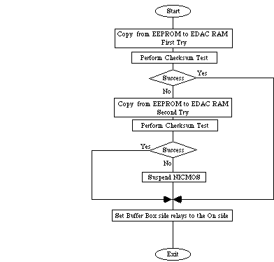
Boot     Operate  normal          * Clear the checksum error flag (NFCKSMFL) [in PSTOL only] *      
                  activation      Copy NICMOS Operate code from EEPROM to EDAC RAM * Verify         
                  sequence for    successful copy operation using checksum * If unsuccessful copy   
                  detector        operation: attempt one retry (suspend on second failure) * Set    
                  imaging         buffer box side relays to the on side * Patch limit check         
                  Note: Warm-up   values in EDAC if necessary * Activate the Operate code (~10      
                  is required     seconds prior to the major frame) Note: the NSSC-I will send      
                  for the DES     TDF status to the flight software during this mode trans. *       
                  electronics     Initialize the software: + Enable paging tables  + Enable reset   
                  and the PAM     on multi-bit error + Enable auto correction for single bit        
                  sensors prior   errors + Enable software refresh of EDAC RAM + Patch Buffer Box   
                  to use. A       limit check flag to 'on' for each box + Enable limit checking     
                  warm-up time    + Restore motor commutations  + Move the FOM to its default       
                  of 1 hour is    position  + Move the Filter Wheels to the blank (opaque)          
                  anticipated     position + Enable the 3 FPA temperature sensors + Set the         
                  starting when   voltages for each detector + Enable the voltages for each         
                  the Operate     detector + Patch Detector Voltage limit check flag to 'on' for    
                  relay is        each detector + Initialize the detector gains + Start auto        
                  closed in the   reset on each detector + Time code update (sync HST and NICMOS    
                  HOLD to BOOT    time counters at least 5 seconds prior to the major frame) +      
                  transition.     Initialize image header buffers (after next major frame)          
                  --------------                                                                    
                  ------- Check                                                                     
                  Dates:  PSTOL                                                                     
                  _8/4/95_                                                                          
                  Instruct                                                                          
                  __5/4/95_                                                                         
         Hold     activation      * Disable the NICMOS science data interface * Disable NFMACRO     
                  error or        (AP-22)  * Disable (open) the Operate relays * Disable NFCSCOMM   
                  normal          (AP-21)  + Note: PSTOL processing requires this step to occur     
                  termination     before opening the Operate relays or a NFCSCOMM tlm timeout       
                  sequence        error might occur. * Clear the Checksum error flag in the NSSC-I  
                  --------------                                                                    
                  ------- Check                                                                     
                  Dates:  PSTOL                                                                     
                  _5/16/95_                                                                         
                  Instruct                                                                          
                  __5/4/95_                                                                         
SUSPEND  HOLD     error           Note: the starting point for this transition is as defined by     
                  recovery        the SUSPEND sequence. * Real-time ground operations (as           
                  --------------  required): Halt & inhibit any RTCS's which might have been        
                  ------- Check   interrupted by the suspend transition * Halt & inhibit unique     
                  Dates:  PSTOL   and suspend RTCS sequences * Clear the sequence request bits *    
                  _5/16/95_       Enable NICMOS RTCS processing * Disable the NICMOS science data   
                  Instruct        interface * Disable NFMACRO (AP-22)  * Disable (open) the         
                  __5/9/95_       Operate relays * Disable NFCSCOMM (AP-21) * Clear the checksum    
                                  error flag * Clear the SUSPEND flag                               

SI Level Mode Transition Table cont.

Current  Next       Transition                                 Action                               
 Mode    Mode         Event                                                                         
Operate  Observe  Normal          * disable the 3 FPA temperature sensors  * calibrate the DES      
                  imaging         analog to digital converters                                      
                  operations                                                                        
                  --------------                                                                    
                  ------- Check                                                                     
                  Dates:  PSTOL                                                                     
                  _5/16/95_                                                                         
                  Instruct                                                                          
                  __5/4/95_                                                                         
         BOOT     normal          * Patch Detector Voltage limit check flag to 'off' for each       
                  termination     detector * Operate (disable) voltages for all detectors * Save    
                  sequence        motor commutation (NCPY2EE) * Patch Buffer Box limit check flag   
                  --------------  to 'off' for each box * Set buffer boxes to the off side *        
                  ------- Check   Issue H/W (RIU) reset   (sync TLM) * Initialize the NICMOS BOOT   
                  Dates:  PSTOL   software: + Disable bus wait state + Enable watchdog timer +      
                  ________        Enable EDAC detection + Enable reset on multi-bit errors +        
                  Instruct        Enable auto correction of single bit errors + Enable software     
                  __5/4/95_       refresh of EDAC RAM + Enable A/D collection + Patch limit check   
                                  values in EDAC if necessary + Turn on CS limit checking +         
                                  Enable science data interface                                     
Observe  Operate  Termination     * move filter wheels to default positions (blank) * enable the    
                  of imaging      3 FPA temperature sensors     Suppression time: 10 minutes        
                  operations                                                                        
                  --------------                                                                    
                  ------- Check                                                                     
                  Dates:  PSTOL                                                                     
                  _5/19/95_                                                                         
                  Instruct                                                                          
                  __5/4/95_                                                                         

SI Level Mode Transition Table cont.

Current  Next       Transition                                 Action                               
 Mode    Mode         Event                                                                         
HOLD,    Safe     system error    * Set RIU A & B to Standby 1 * Disable science data interface     
or       (ambien  or test         * Configure NICMOS for OFF Mode on side 1 using both RIU A &      
BOOT,    t)       termination     RIU B: + disable side 1 & 2 Operate power relays + disable side   
or                sequence due    1 & 2 Hold power relays + disable side 1 & 2 Thermal Controller   
OPERATE           to H/W limit    power relays + set the TEC power side select relay to side 2 +    
, or              violation,      disable TEC Inner V2 & V3 power relays + disable TEC Outer        
OBSERVE           S/W error       power relay + disable PAM sensors (DITS & LVDT) power relay +     
                  condition,      set Pressure Transducer power relay to side 2 + set the Buffer    
                  HST request,    Box relays to side 2 * Disable NFCSCOMM (AP-21) , NFMACRO         
                  or ground       (AP-22) & NSAFING (AP-23)  * Set RIU A to Standby 2 & RIU B to    
                  command         Standby 1                                                         
                  --------------                                                                    
                  ------- Check                                                                     
                  Date:  PLCP                                                                       
                  _8/2/95_                                                                          
HOLD,    Safe     system error    * Set RIU A & B to Standby 1 * Disable science data interface     
or       (flight  or test         * Configure NICMOS for SAFE Mode on side 1 using both RIU A &     
BOOT,    )        termination     RIU B: + disable side 1 & 2 Operate power relays + disable side   
or                sequence due    2 Hold power relay + enable side 1 Hold power relay + disable     
OPERATE           to H/W limit    side 2 Thermal Controller power relay + enable side 1 Thermal     
, or              violation,      Controller power relay  + set the TEC power side select relay     
OBSERVE           S/W error       to side 1 + enable TEC Inner V2 & V3 power relays + enable TEC    
                  condition,      Outer power relay + disable PAM sensors (DITS & LVDT) power       
                  HST request,    relay + set the Pressure Transducer power relay to side 1 + set   
                  or ground       the Buffer Box relays to side 2 * Disable NFCSCOMM (AP-21) ,      
                  command         NFMACRO (AP-22) & NSAFING (AP-23)  * Set RIU A to Standby 2 &     
                  --------------  RIU B to Standby 1                                                
                  ------- Check                                                                     
                  Date:  PLCP                                                                       
                  _8/2/95_                                                                          
Operate  Boot     system error    * Set the SUSPEND state flag in the NSSC-I * Issue H/W RIU        
, or     (suspen  due to S/W      reset for MEB 1 & 2 using both RIUA and RIUB * Set Buffer Boxes   
Observe  d)       error           to the off side using both RIUA and RIUB * Disable the PAM        
                  condition,      sensors (DITS & LVDT) * Disable NFMACRO (AP-22)  * Initialize     
                  limit           the Boot software after it has come up: + Disable bus wait        
                  failure, or     state + Enable the watch dog timer + Enable EDAC detection +      
                  ground          Enable EDAC reset on multi-bit error + Enable EDAC H/W            
                  command.        correction for single bit errors + Enable A/D collection + Turn   
                  --------------  on CS limit checking + Enable EDAC S/W refresh * Disable          
                  ------- Check   science data interface * Disable all NICMOS RTCS processing       
                  Date:  PLCP                                                                       
                  __8/3/95_                                                                         

SI Level Mode Transition Table cont.

Current  Next       Transition                                 Action                               
 Mode    Mode         Event                                                                         
Lamp     lamp1    Lamp            Activate Calibration Lamp #1 (State = On)                         
hold              activation                                                                        
         lamp2    Lamp            Activate Calibration Lamp #2 (State = On)                         
                  activation                                                                        
         lamp3    Lamp            Activate Calibration Lamp #3 (State = On)                         
                  activation                                                                        
LAMP1    Lamp     Lamp off        Deactivate Calibration Lamp #1 (State = Off)                      
         hold                                                                                       
LAMP2    Lamp     Lamp off        Deactivate Calibration Lamp #2 (State = Off)                      
         hold                                                                                       
LAMP3    Lamp     Lamp off        Deactivate Calibration Lamp #3 (State = Off)                      
         hold                                                                                       
PAM      PAM ON   PAM activation  * Activate the PAM sensors: LVDT focus & DITS tilt  * Specify     
HOLD                              the PAM 'On' limits by setting the PAM on/off flag to 1 (non      
                                  zero)                                                             
PAM ON   PAM      PAM             * Specify the PAM 'Off' limits by setting the PAM on/off flag     
         HOLD     deactivation    to 0 (zero) * Deactivate the PAM sensors: LVDT focus & DITS       
                                  tilt                                                              

3.4 NICMOS Component States Information

The following tables define the state of all NICMOS commandable items, as they relate to the defined modes. The tables are organized by NICMOS component.

NICMOS Component: Remote Interface Unit (RIU)

Component Item or                         Science Instrument Modes Component Item State              
Commandable Action             OFF       LAUNCH    SAFE      HOLD      BOOT      OPERATE   OBSERVE   
                                         CONFIG                                                      
HST PDU RIU-A (primary) Power  off       => off    => on     on        on        on        on        
HST PDU RIU-B (redundant)      off       => off    on        on        on        on        on        
Power                                                                                                
RIU-A Mode Select              stndby2   =>        =>        stndby2   stndby2   stndby2   stndby2   
                                         stndby2   stndby2                                           
RIU-B Mode Select              stndby1   =>        =>        stndby1   stndby1   stndby1   stndby1   
                                         stndby1   stndby1                                           
                                                                                                     

Note: The command block must transition RIU-A through standby 1 to standby 2. When RIU-A is placed in standby 2, RIU-B is automatically set to off. RIU-B is then set to standby 1.

NICMOS Component: Buffer Box (BB)

Component Item or                         Science Instrument Modes Component Item State              
Commandable Action             OFF       LAUNCH    SAFE      HOLD      BOOT      OPERATE   OBSERVE   
                                         CONFIG                                                      
Power, Control & Data signal   side 2    side 2    side 2    =>side    side 2    => side   side 1    
Path    - Buffer Box #1    -   <=                  <=        2<=       <=        1                   
side relay for detector half                                                                         
A    - side relay for                                                                                
detector half B                                                                                      
Power, Control & Data signal   side 2    side 2    side 2    =>side    side 2    => side   side 1    
Path    - Buffer Box #2    -   <=                  <=        2<=       <=        1                   
side relay for detector half                                                                         
A    - side relay for                                                                                
detector half B                                                                                      
Power, Control & Data signal   side 2    side 2    side 2    =>side    side 2    => side   side 1    
Path    - Buffer Box #3    -   <=                  <=        2<=       <=        1                   
side relay for detector half                                                                         
A    - side relay for                                                                                
detector half B                                                                                      
                                                                                                     

=> X  cmd required when transitioning from a    X <=  cmd required when transitioning from   
      lower mode                                      a higher mode                          

NICMOS Component: Detector Electronics (DES)

Component Item or                         Science Instrument Modes Component Item State              
Commandable Action             OFF       LAUNCH    SAFE      HOLD      BOOT      OPERATE   OBSERVE   
                                         CONFIG                                                      
output source follower bias    0 volts   0 volts   0 volts   0 volts   0 volts   => 5      5 volts   
(1-3)                                                                  <=        volts               
diode bias (1-3)               0 volts   0 volts   0 volts   0 volts   0 volts   => 5      5 volts   
                                                                       <=        volts               
shift register digital bias    0 volts   0 volts   0 volts   0 volts   0 volts   => 5      5 volts   
(1-3)                                                                  <=        volts               
reset bias (1-3)               0 volts   0 volts   0 volts   0 volts   0 volts   => 5      5 volts   
                                                                       <=        volts               
column select buffer bias      0 volts   0 volts   0 volts   0 volts   0 volts   => 5      5 volts   
(1-3)                                                                  <=        volts               
source follower pull-up        0 volts   0 volts   0 volts   0 volts   0 volts   => 5      5 volts   
voltage (1-3)                                                          <=        volts               
offset subtraction voltage     0 volts   0 volts   0 volts   0 volts   0 volts   => 5      5 volts   
(1-3)                                                                  <=        volts               
                                                                                                     
FPA internal temperature       disable   =>        disable   disable   disable   =>        =>        
monitor (1-3) Note: on only              disable                       <=        enable    disable   
when taking a reading                                                            (disable            
                                                                                 after               
                                                                                 warm-up)            
                                                                                                     
VD enabled to detector (1-3)   disable   disable   disable   disable   disable   =>        enable    
(A-B)                                                                  <=        enable              
DETBIAS enabled to detector    disable   disable   disable   disable   disable   =>        enable    
(1-3) (A-B)                                                            <=        enable              
VSOURCE, OFFSET enabled to     disable   disable   disable   disable   disable   =>        enable    
detector (1-3) (A-B)                                                   <=        enable              
VDD enabled to detector        disable   disable   disable   disable   disable   =>        enable    
(1-3) (A-B)                                                            <=        enable              
AHI enabled to detector        disable   disable   disable   disable   disable   =>        enable    
(1-3) (A-B)                                                            <=        enable              
RHI enabled to detector        disable   disable   disable   disable   disable   =>        enable    
(1-3) (A-B)                                                            <=        enable              
video gain (1-3)               not set   not set   not set   not set   not set   => set    set       
video bandwidth (1-3)          not set   not set   not set   not set   not set   => set    set       
                                                                                                     

=> X  cmd required when transitioning from a    X <=  cmd required when transitioning from   
      lower mode                                      a higher mode                          

NICMOS Component: Low Voltage Power Supply (LVPS)

Component Item or                         Science Instrument Modes Component Item State              
Commandable Action             OFF       LAUNCH    SAFE      HOLD      BOOT      OPERATE   OBSERVE   
                                         CONFIG                                                      
Hold power bus relay -         open <=   =>        closed    closed    closed    closed    closed    
heater controllers relay -               closed                                                      
TEC side select relay -                                                                              
pressure transducer side                                                                             
select relay - SES tlm                                                                               
isolation amp                                                                                        
Operate power bus relay -      open <=   => open   open <=   open      =>        closed    closed    
DES /Buffer box supply -                                               closed                        
SES/CS supply -                                                                                      
mechanical/cal lamp supply                                                                           
Thermal Controller power       open <=   =>        closed    closed    closed    closed    closed    
relay - side A and B heater              closed                                                      
controller sets                                                                                      
Pressure Transducer power      side 2    => side   side 1    side 1    side 1    side 1    side 1    
relay - Nitrogen flow rate     <=        1                                                           
monitor                                                                                              
TEC Power side select relay    side 2    => side   =>side 1  side 1    side 1    side 1    side 1    
                               <=        2                                                           
TEC Outer power relay          open<=    => open   =>closed  closed    closed    closed    closed    
TEC Inner V2 power relay       open<=    => open   =>closed  closed    closed    closed    closed    
TEC Inner V3 power relay       open<=    => open   =>closed  closed    closed    closed    closed    
                                                                                                     

=> X  cmd required when transitioning from a    X <=  cmd required when transitioning from   
      lower mode                                      a higher mode                          

Support Electronics Section (SES)

Component Item or                         Science Instrument Modes Component Item State              
Commandable Action             OFF       LAUNCH    SAFE      HOLD      BOOT      OPERATE   OBSERVE   
                                         CONFIG                                                      
Calibration Lamp Activation    off       off       off       off       off       => off    off       
- memory mapped I/O from CS                                                                          
- specify lamp 1-3 (SES/SI                                                                           
side A)                                                                                              
                                                                                                     
PAM X and Y motor              not       not       not       stored    stored    =>        loaded    
commutations    - loaded:      loaded    loaded    loaded              <=        loaded              
EDAC to memory map    -                                                                              
stored: in EEPROM from EDAC                                                                          
PAM position                   default   default   default   default   default   default   default   
FOM X, Y mechanism             not       not       not       stored    stored    =>        loaded    
commutation                    loaded    loaded    loaded              <=        loaded              
FOM position                   default   default   default   default   default   =>        n/a       
                                                                                 default             
Filter wheels mechanism        not       not       not       stored    stored    =>        loaded    
commutation                    loaded    loaded    loaded              <=        loaded              
Filter Wheels positions        default   default   default   default   default   =>        n/a       
                                                                                 default             
Thermal Controller Set Point   not       not       loaded    loaded    loaded    loaded    loaded    
- memory mapped I/O from CS    loaded    loaded                                                      
RTD Dewar Temperature          side 1    => side   side 1    side 1    side 1    side 1    side 1    
Sensors                        <=        1                                                           
Side select power relay for    side 1    => side   side 1    side 1    side 1    side 1    side 1    
non-redundant sensors:    -    <=        1                                                           
PAM tilt & focus sensors                                                                             
- Pressure transducer    -                                                                           
RTD Dewer                                                                                            
DITS & LVDT power relay        open      open      open      open      open <=   =>        closed    
                                                                                 closed              

NICMOS AP's

Component Item or                         Science Instrument Modes Component Item State              
Commandable Action             OFF       LAUNCH    SAFE      HOLD      BOOT      OPERATE   OBSERVE   
                                         CONFIG                                                      
NFCSCOMM (AP-21)               disabled  disabled  disable   disabled  =>        enabled   enabled   
                                                   <=                  enable                        
NFMACRO    (AP-22)             disabled  disabled  disable   disabled  =>        enabled   enabled   
                                                   <=                  enable                        
NFSAFING    (AP-23)            disabled  disabled  disable   =>        enabled   enabled   enabled   
                                                   <=        enable                                  


=> X  cmd required when transitioning from a    X <=  cmd required when transitioning from   
      lower mode                                      a higher mode                          

4.0 OPERATIONS DESCRIPTION TIMING AND CONSTRAINTS

This section provides a description of the instrument operations in the OBSERVE mode and provides the detailed command function and timing information for all NICMOS stored commands. Before the function and timing tables are introduced, review the OBSERVE mode operations shown in Figures 4.0-1 and 4.0-2 below. These figures define the rules associated with the generation of commands for the NICMOS instrument.

Figure 4.0-1 Detector Operations Control Flow

Figure 4.0-2 Detector Operations Control Flow

4.1 NSSC-I Command Processing Functions and Timing Definition

Table 4.1-1 Timing Data for NSSC-I Command Processing & NICMOS FSW MAR Activation

                      Function                                 Time Required (sec)            
  1  NSSC-I Executive absolute time command (ATC)      time required = .025 sec (macros w/     
     processing: - at each 1 second activation, move   <= 16 words)                            
     16 command words to one of the 4 Macro AP                                                 
     command buffers                                                                           
  2  The NICMOS Macro AP will be activated either 25   time required (NDETBUFx) macros =       
     msec or 525 msec past the starting time of the    .050 sec time required (NNICBUF)        
     NSSC-I Executive (the discrepancy accounts for    macros = 1.050 sec  Note:  (1) The      
     uncertancies associated with the activation of    time required for macros using the      
     the Macro AP and the ATC processing). NSSC-I      NNICBUF buffer include another second   
     Macro AP requires 0.050 sec and includes: *       which accounts for the fact that        
     unloading one to four macro input buffers         macros using this buffer can be held    
     (NDETBUF1, NDETBUF2, NDETBUF3 and NNICBUF), *     off another cycle if the NDETBUF        
     constructing an RTCS with a maximum size of 145   buffers are full.. See example in the   
     NICMOS commands, and * activating the RTCS        figure below. (2) The timeline in       
                                                       Figure 4.1-1 shows the 25 msec Macro    
                                                       AP activation latency case.             
  3  * NSSC-I Executive relative time command (RTCS)   time required = 0.87 sec                
     processing: At the next 25 msec command                                                   
     processing cycle, start sending the commands in                                           
     the AP unique RTCS to NICMOS at 0.025 sec for                                             
     the first and last command + 3 * 48 * 0.005 sec                                           
     for the rest of the commands for a total of                                               
     0.77 seconds. * Also account for CSCOMM nesting                                           
     this RTCS with either a TDF change RTCS or a                                              
     slew request verify RTCS which will take 0.075                                            
     seconds. * Include the .025 sec RTCS activation                                           
     latency shown below.                                                                      
  4  NICMOS command processing and Task/Function       time required (task activation) =       
     activation: * Complete the command queue          0.0256 sec time required (function      
     loading process = 0.0013 sec * FSW task           activation) = 0.0216 sec Note: Need     
     activation = 0.005 sec * FSW function             to include this time for macros using   
     activation = 0.001 sec * FSW activation           the NDETBUF3 or NICBUF buffers Only     
     hold-off time due to hard real-time task          one occurance of this process is        
     overhead = 0.01934 sec                            accounted for (the NDETBUF3 case),      
                                                       NDETBUF 1&2 processing occurs           
                                                       sinultaneously with RTCS processing.    
                                                       See the figure below.                   
                                                      times in        NDETBUFx    NICBUF        
                                                      seconds                                   
               Total  Processing Time                 TASK             0.971      1.971         
                                                      FUNCTION         0.966      1.966         

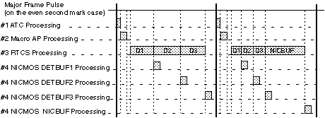
Figure 4.1-1 MAR Command Processing Timeline

4.2 NICMOS Macro Timing Definition

Table 4.2-1 collects the timing information required to process macros within the CS FSW. The 'Ref. No.' column is a reference to this section for further details on the algorithms used to generate the timing data shown in the 'Estimated' column. When the 'Ref. No' column is marked with 'n/a' no further details are to be provided. Actual timing results will be provided in this table as they are measured using test hardware with the following loading characteristics: (1) bus wait state off, (2) EDAC processing on, (3) limit checking on, (4) A/D collection on, (5) watch dog timer processing on, and (6) no parallel operations.

When two times are seperated by a '/'; the first number is the time required for CS FSW Macro Processor utilization (when will it be ready to process the next macro on the input Q), and the second number is the time for the task to complete (including settling and warm-up times).

Table 4.2-1 NICMOS Timing Table

  Macro     Macro Activation Request   Ref.   Timing Data (sec)            Algorithm Summary           
   Name                                No.   Estimated   Actual       ([[section]] = done on start     
                                                                                 macro)                
NABORTM     Abort Current Macro        n/a                                                             
            Processing                                                                                 
NABTWAIT    Abort Wait                 n/a                                                             
NACCUM(x)   Start MIF Exposure         4.2.      /                                                     
                                       6                                                               
NACCUM(x)S  Start MIF with slow                  /                                                     
            bandwidth                                                                                  
NACCUM(x)F  Start MIF with fast                  /                                                     
            bandwidth                                                                                  
NALGDIAG    Collect Analog             n/a       /                                                     
            Diagnostic Data                                                                            
NAUTO(x)    Detector Auto Reset        n/a                                                             
NBRTOBJ(x)  Start Bright Object                  /                                                     
            Exposure                                                                                   
NCALAMP     Operate Calibration Lamp   4.2.     ?/1                                                    
                                       5                                                               
NCHKSUM     Compute Checksum                     /                                                     
NCLEARQS    Clear All Queues           n/a                                                             
NCOMREST    Restore Motor              n/a                                                             
            Commutation                                                                                
NCPY2EE     Copy to EEPROM             n/a       /                                                     
NCPY2RAM    Copy to RAM/EDAC RAM Mem   n/a       /                                                     
NCPY2TPG    Copy to TPG Memory         n/a       /                                                     
NCSRESET    Reset to Boot              n/a       /                                                     
NDA2DENG    Disable A/D Collection     n/a                                                             
NDBWAIT     Disable Bus Wait State     n/a                                                             
NDCSPAGE    Disable CS Paging          n/a                                                             
NDDOGTIM    Disable Watchdog Timer     n/a                                                             
NDEDACCR    Disable EDAC H/W           n/a                                                             
            Correction                                                                                 
NDEDACDT    Disable EDAC H/W           n/a                                                             
            Detection                                                                                  
NDIGDIAG    Collect Digital            n/a       /                                                     
            Diagnostic Data                                                                            
NDLIMITS    Disable Limits Monitoring  n/a                                                             
NDMPMEM     Dump Memory                n/a       /                                                     
NDMRESET    Disable MultiBit Error     n/a                                                             
            Reset                                                                                      
NDREFRSH    Disable S/W Refresh        n/a                                                             
NDTBAND(x)  Set Detector Bandwidth     n/a                                                             
NDTCALIB    Calibrate DES A2D                                      0.4 * # of detectors                
NDTGAIN(x)  Set Detector Gains         n/a                                                             
NDUMPSD     Dump Image                 4.2.      /                                                     
                                       7                                                               
NEA2DENG    Enable A/D Collection                                                                      

Table 4.2-1 NICMOS Timing Table (continued)
  Macro     Macro Activation Request   Ref.   Timing Data (sec)             Algorithm Summary           
   Name                                No.   Estimated   Actual    ([[section]] = done on start macro)  
NEBWAIT     Enable Bus Wait State                                                                       
NECSPAGE    Enable CS Paging           n/a                                                              
NEDOGTIM    Enable Watchdog Timer      n/a                                                              
NEEDACCR    Enable EDAC H/W            n/a                                                              
            Correction                                                                                  
NEEDACDT    Enable EDAC Detection                                                                       
NELIMITS    Enable Limits Monitoring   n/a                                                              
NEMRESET    Enable H/W MultiBit        n/a                                                              
            Error Reset                                                                                 
NEREFRSH    Enable S/W Refresh         n/a                                                              
NFOMABS     Move FOM to Absolute       4.2.                                                             
            Position                   1                                                                
NFOMREL     Move FOM to Relative       4.2.                                                             
            Position                   2                                                                
NFPATMP     Operate FPA Temperature    n/a                                                              
            Sensor                                                                                      
NFWABS(x)   Move Filter Wheel to       4.2.      /                                                      
            Absolute Position          3                                                                
NFWREL(x)   Move Filter Wheel to       4.2.      /                                                      
            Relative Position          4                                                                
NIMMNOOP    NO-OP Immediate            n/a                                                              
NINITSD     Initialize Image/Header                                                                     
            Buffers                                                                                     
NJMP2OPR    Jump to Operate            n/a       /                                                      
NLDCS       Load CS Memory-Mapped I/O  n/a                                                              
NLDDES      Load DES Memory-Mapped     n/a                                                              
            I/O                                                                                         
NLDEDAC     Load EDAC RAM Variable               /                                                      
NLDEDACF    Load EDAC RAM Fixed        n/a       /                                                      
NLDSES      Load SES Memory-Mapped     n/a       /                                                      
            I/O                                                                                         
NMEMMON     Install Memory Monitor     n/a                                                              
NMULTI(x)   Start Multi-Accum                    /                                                      
            Exposure                                                                                    
NMULTI(x)S  Start Multi with slow                /                                                      
            bandwidth                                                                                   
NMULTI(x)F  Start Multi with fast                /                                                      
            bandwidth                                                                                   
NNORNOOP    NO-OP Normal               n/a                                                              
NOPRVLT     Operate Detector           n/a                                                              
            Voltages                                                                                    
NPAMFCS     Move PAM Focus                                                                              
NPAMTILT    Move PAM to Relative                                                                        
            Position                                                                                    
NRAMP(x)    Start Ramp Exposure        4.2.      /                                                      
                                       8                                                                
NRESTSD     Reset SD Dump Pointers               /                                                      
NRAMP(x)S   Start Ramp with slow                 /                                                      
            bandwidth                                                                                   
NRAMP(x)F   Start Ramp with fast                 /                                                      
            bandwidth                                                                                   
NSELFTST    Perform Self-test                    /                                                      
NSETHEAT    Set Heater Setpoint        n/a                                                              
NSETVLT     Set Detector Voltage       n/a                                                              
NSLEWACK    CSCOMM Slew Confirmation   n/a                                                              
NTARACQ     Perform Target                                                                              
            Acquisition                                                                                 
NTCUPDTE    Time Code Update           n/a      n/a        n/a                                          
NTDFDOWN    Take Data Flag Down        n/a      n/a        n/a                                          
NTDFUP      Take Data Flag Up          n/a      n/a        n/a                                          
NTPG2RAM    Collect TPG Memory                                                                          
NWAIT       Wait                       n/a                                                              

4.2.1 NFOMABS Move FOM to Absolute Position

Command Block:   NFOMABS          Title:   Move FOM to Absolute Position                      
Description:   Move the FOM, from its current position, to a new position specified in arc    
seconds at the mechanism mirror                                                               
Constraints:    * Only one axis can be specified for each instantiation of this command       
block. * The CS FSW will reject a FOM move request if any other mechanism is in motion.       
                  Function                                  Time Required (sec)               
  1  NFOMABS macro command processing in the    time required = 2 seconds Assume worst case    
     NSSC-I                                     command loading at the NSSC-I. See Table       
                                                4.1-1 for more information on NSSC-I loading   
  2  NFOMABS macro command processing in the    time required = .010 seconds See Table 4.1-1   
     CS FSW The FOM move software is            for more information                           
     implemented as a 'function'                                                               
  3  Drive the FOM using the parameters         time required = (see formula at left)          
     specified. time required = # steps to                                                     
     move / motor step rate # steps to move =                                                  
     # arc sec to move / arc sec per step #                                                    
     arc sec to move = ABS ( desired position                                                  
     in arc sec - current position in arc                                                      
     sec) arc sec per step = 0.5 (worst case)                                                  
     worst case of max FOM move using the                                                      
     above formula is TBD seconds                                                              
                                                                                               
                 Total Time                    sum of the values computed above               

4.2.2 NFOMREL Move FOM to Relative Position

Command Block:   NFOMREL          Title:   Move FOM to Relative Position                      
Description:   Move the FOM, relative to its current position, to a new position specified    
as a number of steps                                                                          
Constraints:    * Only one axis can be specified for each instantiation of this command       
block. * The FOM step size is 0.51 to 1.01 arc seconds depending on the current location      
within the field of travel. * The CS FSW will reject a FOM move request if any other          
mechanism is in motion.                                                                       
                  Function                                  Time Required (sec)               
  1  NFOMREL macro command processing in the    time required = 2 seconds Assume worst case    
     NSSC-I                                     command loading at the NSSC-I. See Table       
                                                4.1-1 for more information on NSSC-I loading   
  2  NFOMREL macro command processing in the    time required = .010 seconds See Table 4.1-1   
     CS FSW The FOM move software is            for more information                           
     implemented as a 'function'                                                               
  3  Drive the FOM using the parameters         time required = commanded steps to move /      
     specified. Worst case = max move size /    motor step rate                                
     motor step rate                                                                           
                                                                                               
                 Total Time                    sum of the values computed above               

4.2.3 NFWABS Move Filter Wheel to Absolute Position

Command Block:   NFWABS           Title:   Move Filter Wheel to Absolute Position             
Description:   This command block will move the filter wheel to a position specified as a     
specific filter name.                                                                         
Constraints:    * The CS FSW will reject a request to move a filter wheel if its associated   
detector is currently tasked for an exposure. * The preferred direction for the filter        
wheel is clockwise (viewed from the wheel end of the rotation axis) to assure                 
repeatability. The CS FSW however, will move the filter wheel clockwise or counter            
clockwise depending on which direction is closer to the desired destination. When a counter   
clockwise movement is used, the CS FSW will over-shoot the desired destination by some        
number of motor steps, and then rotate the wheel back clockwise as required to obtain the     
final position.                                                                               
                  Function                                  Time Required (sec)               
  1  NFWABS macro command processing in the     time required = 2 seconds Assume worst case    
     NSSC-I                                     command loading at the NSSC-I. See Table       
                                                4.1-1 for more information on NSSC-I loading   
  2  NFWABS macro command processing in the     time required = .015 seconds See Table 4.1-1   
     CS FSW The filter wheel move software is   for more information                           
     implemented as a 'task'                                                                   
  3  Move the filter wheel number of steps      time1 = (nfilters *  number of steps           
     filter to filter = 60  number of           filter-to-filter) / filter wheel steps per     
     over-shoot steps = 3 task activation pad   second if direction = clockwise    time        
     = .005 sec  [[Delta]] = desired filter     required = time1  else    time required =      
     no. - current filter no. if [[Delta]] >=   (time1 + number of over-shoot steps / filter   
     0     if [[Delta]] > 10       direction    wheel steps per second) + a task activation    
     = counter clockwise       nfilters = 20    pad   Notes: * is the wheel instantly          
     - [[Delta]]    else       direction =      reversible? ==> yes * account for wheel        
     clockwise       nfilters = [[Delta]]       vibration settle time? ==> yes (3 sec) *       
     endif else     if [[Delta]] < -10          include case when the requested location =     
     direction = clockwise       nfilters =     the current location * include time for        
     20 - current filter no. + desired filter   retry ==> yes (set to 0) * the time required   
     no.    else       direction = counter      equation above should include 2 times the      
     clockwise       nfilters = ABS             number of over-shoot steps ?? ==> yes          
     ([[Delta]])    endif endif                                                                
                                                                                               
                 Total Time                    sum of the values computed above               

4.2.4 NFWREL Move Filter Wheel to Relative Position

Command Block:   NFWREL           Title:   Move Filter Wheel to Relative Position             
Description:   This command block will move the filter wheel to a position specified as an    
offset from the current position in mechanism motor steps.                                    
Constraints:    * The flight software will reject a request to move a filter wheel if its     
associated detector is currently tasked for an exposure.                                      
                  Function                                  Time Required (sec)               
  1  NFWREL macro command processing in the     time required = 2 seconds Assume worst case    
     NSSC-I                                     command loading at the NSSC-I. See Table       
                                                4.1-1 for more information on NSSC-I loading   
  2  NFWREL macro command processing in the     time required = .015 seconds See Table 4.1-1   
     CS FSW The filter wheel move software is   for more information                           
     implemented as a 'task'                                                                   
  3  Move the filter wheel wheel speed = 120    time required = # selected steps / wheel       
     steps per second                           speed                                          
                                                                                               
                 Total Time                    sum of the values computed above               

4.2.5 NCALAMP Operate Calibration Lamp

Command Block:   NCALAMP          Title:   Operate Calibration Lamp                           
Description:   This command block will activate or deactivate the selected calibration lamp   
Constraints:    * The ability to illuminate more than one calibration lamp at a time is a     
CS FSW table selectable parameter. The default setting is to allow only one lamp to be on     
at a time. The CS FSW will enforce the one lamp rule by automatically turning off the         
unselected lamps.                                                                             
                  Function                                  Time Required (sec)               
  1  NCALAMP macro command processing in the    time required = 2 seconds Assume worst case    
     NSSC-I                                     command loading at the NSSC-I. See Table       
                                                4.1-1 for more information on NSSC-I loading   
  2  NCALAMP macro command processing in the    time required = .010 seconds See Table 4.1-1   
     CS FSW The lamp activate/deactivate        for more information                           
     software is implemented as a 'function'                                                   
  3  * Generate the SES memory map command      time required = .005  Question:  * is there    
     from the data in the NCALAMP command *     a stabilization time for the lamp flux ?,      
     Write the command to SES shared memory     and * is it the same for all three lamps?      
     * Include logic for table access and                                                      
     command bit construction for multiple                                                     
     lamp activations                                                                          
  4  Lamp flux stabilization time               300 seconds (5 minutes => estimate from        
                                                optics group) Note: use the same time for      
                                                all three lamps                                
                 Total Time                                   302.015 seconds                 

4.2.6 ACCUM Exposure Sequence

Command Block:   NACCUM(xx)       Title:   Exposure Sequence ==> ACCUM                        
Description:   This exposure sequence includes a single integration period surrounded by      
multiple non-destructive detector reads. The process is defined as follows: * upon receipt    
of the NACCUM command, terminate the auto-flush, and initiate a predefined number of          
detector resets, * build the image header and allocate CS buffer memory for the image data,   
* perform the specified number of detector reads and coadd each image on a pixel by pixel     
basis, * integrate on the detector for the commanded period of time, * as above, perform      
the specified number of detector reads and coadd each image on a pixel by pixel basis, *      
difference the initial and final coadded images, then form the average difference, * store    
the averagedifferences into CS buffer memory and update the header to indicate that the       
image is complete.                                                                            
Constraints:    * The SI mode should be OBSERVE. If the ACCUM command is used during the      
OPERATE mode the image results will be affected by the FPA temperature sensor. * The          
commanded detector software will reject any additional image requests until all of the        
functions listed below have completed. * If TPG expose time = 0 then NREAD must = 1.          
                  Function                                  Time Required (sec)               
  1  NACCUM macro command processing in the     time required = 2 seconds Assume worst case    
     NSSC-I                                     command loading at the NSSC-I. See Table       
                                                4.1-1 for more information on NSSC-I loading   
  2  NACCUM macro command processing in the     time required = .020 seconds See Table 4.1-1   
     CS FSW The ACCUM software is implemented   for more information                           
     as a 'task'                                                                               
  3  Detector flush sequence (3 flushes are     if readout speed is "FAST"    time required    
     required) The first two flushes will be    = 0.615 seconds else    time required =        
     performed at the "fast" readout speed      0.410 + 2.050 seconds = 2.460 seconds endif    
     (0.205 seconds/flush), while the third     Note:  need to add rules for multi detector    
     flush will be done at the same readout     operations.                                    
     speed as the science exposure.  A slow                                                    
     readout speed will require ten times                                                      
     longer to read the detector A flush time                                                  
     of .205 seconds per detector flush at                                                     
     the fast readout speed is based on a                                                      
     selected pixel clocking rate of 80 kHz.                                                   
     This rate provides an effective pixel                                                     
     access time of 12.5 usec. (1/80000).                                                      
     With 128 x 128 access required to                                                         
     address the complete array, the                                                           
     following equation gives the                                                              
     flush/readout time required: (128 * 128)                                                  
     * (1/80000) The detector flush/readout                                                    
     time can be changed by selecting a                                                        
     different pixel clocking rate using the                                                   
     Timing Pattern Generator SubPattern                                                       
     Editor. The Users Manual for this                                                         
     equipment is located in NICMOS SER                                                        
     SW-089.                                                                                   
  4  Initial image generation NREAD =           if NREAD = 1                   time required   
     Commanded number of initial detector       = .Detector readout time   else    time        
     reads Detector readout time = .205 sec     required = (Detector readout time * NREAD) +   
     at the fast readout      speed, and        (.500 * (NREAD - 1))    if TPG expose time <   
     2.050 seconds at the slow readout speed    .500       time required = time required +     
     (see function 3 above) Image co-add time   .500 - TPG expose time                         
     = .500 sec                                                                                
  5  TPG expose time                            time required = NACCUM command parameter:      
                                                TPGEXP                                         

Continued on next page.

ACCUM Exposure Sequence (continued)

                  Function                                  Time Required (sec)               
  6  Final image generation  See notes in       if NREAD = 1    time required = Detector       
     Function #3                                readout time  else    time required =          
                                                (Detector readout time * NREAD) +              
                                                (.500 * NREAD)                                 
  7  Difference the final and initial images,   time required = 1.250 seconds Question: is     
     average the difference, and store the      there a timing difference if the reult is      
     results into buffer memory  Image          negative?                                      
     difference & memory store time = .500                                                     
     sec Image averaging time = .750 sec                                                       
  8  Pad for possible take data flag            time required = 2 * Detector readout time      
     processing = post processing (co-add)      Question: should we account for more than      
     time for the data obtained in the two      one TDF down/up cycle?                         
     additional reads of the detector. (TDFdn                                                  
     & TDFup) (TDFdn - MIavg) + ( MFavg -                                                      
     TDFup)                                                                                    
                 Total Time                    sum of the values computed above based on      
                                               image specific settings                        

Figure 4.2.6-1 is a sample timeline for an NACCUM exposure sequence with the number of initial and final reads (NREAD) set to 2. This example also shows an exposure duration which is longer than the initial coadd and averageing periods. In the figure, the # numbers correspond to the function numbers in the tables shown above.

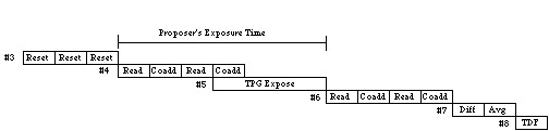
Figure 4.2.6-1 ACCUM Exposure Sequence

4.2.7 NDUMPSD Dump Image

Command Block:   NDUMPSD          Title:   Dump Image                                         
Description:   This command will initiate the downlink of a specified number of 'images'      
from RAM. Images can be detector image data, and/or engineering diagnostic data, and/or TPG   
memory data.                                                                                  
Constraints:    * TBD                                                                         
                  Function                                  Time Required (sec)               
  1  NDUMPSD macro command processing in the    time required = 2 seconds Assume worst case    
     NSSC-I                                     command loading at the NSSC-I. See Table       
                                                4.1-1 for more information on NSSC-I loading   
  2  NDUMPSD macro command processing in the    time required = .015 seconds See Table 4.1-1   
     CS FSW The dump image software is          for more information                           
     implemented as a 'task'                                                                   
  3  * Initialize the SDF interface *           time required to process the NDUMPSD command   
     Generate science data header * Write 4K    and be available for another command (except   
     of header and science or memory dump       for a NDUMPSD command) = 1.000 second          
     data to the output FIFO * Start the                                                       
     output process and enable the science                                                     
     data required interrupt                                                                   
  4  * Respond to the science data interrupt    time required to complete the output of the    
     by loading the next 2K of image data to    requested number of images to the tape         
     the FIFO  The effective output rate to     recorder = the number of 16 bit words to       
     the C&DH = 65536 words/second @ 1 MHz      output / the effective output rate + a pad     
     downlink  Refer to the ST-ICD-08 NICMOS    for Reed Soloman encoding and packet overhead  
     Unique Appendix for a description of the                                                  
     format of the science data.                                                               
                                                                                               
                 Total Time                    see above                                      

4.2.8 RAMP Exposure Sequence

Command Block:   NRAMP(xx)        Title:   Exposure Sequence ==> RAMP                         
Description:   This exposure sequence provides for up to 255 detector readouts resulting in   
two 256x256x16bit images. The first image contains a slope value of charge accumulation       
computed for each pixel, and the second image array contains two eight bit quantities which   
correspond to the pixel data in the first image array. This first byte of the two byte        
image array will be the number of samples (intermediate readouts) used in computing the       
corresponding pixel's value, and the second byte will be the variance of the data scaled to   
eight bit precision.   The imaging process can be summarized as follows: * upon receipt of    
the NRAMP command, build a single image header and allocate memory for the two images, *      
terminate the detector auto-flush sequence, and initiate a predefined number of resets, *     
perform the specified number of detector reads using the exposure time specified in the MAR   
between each read, * after each read (during the subsequent exposure period) the flight       
software will compute the slope of each pixel, and update the number of samples and the       
variance (sigma-squared) arrays, * continue this process until the number of detector reads   
equals the number specified in the MAR, and * post exposure processing includes copying the   
slope image array values from scratch pad memory to the image buffer queue.                   
Constraints:                                                                                  
                  Function                                  Time Required (sec)               
  1  Build the image header and allocate        time required = 20 msec                        
     memory for the two images                                                                 
  2  Detector flush sequence (3 flushes are     if readout speed is "FAST"    time required    
     required) The first two flushes will be    = 0.615 seconds else    time required =        
     performed at the "fast" readout speed      0.410 + 2.050 seconds = 2.460 seconds endif    
     (0.205 seconds/flush), while the third     Note:  need to add rules for multi detector    
     flush will be done at the same readout     operations.                                    
     speed as the science exposure.  A slow                                                    
     readout speed will require ten times                                                      
     longer to read the detector A flush time                                                  
     of .205 seconds per detector flush at                                                     
     the fast readout speed is based on a                                                      
     selected pixel clocking rate of 80 kHz.                                                   
     This rate provides an effective pixel                                                     
     access time of 12.5 usec. (1/80000).                                                      
     With 128 x 128 access required to                                                         
     address the complete array, the                                                           
     following equation gives the                                                              
     flush/readout time required: (128 * 128)                                                  
     * (1/80000) The detector flush/readout                                                    
     time can be changed by selecting a                                                        
     different pixel clocking rate using the                                                   
     Timing Pattern Generator SubPattern                                                       
     Editor. The Users Manual for this                                                         
     equipment is located in NICMOS SER                                                        
     SW-089.                                                                                   

Continued on next page.

RAMP Exposure Sequence (continued)

                  Function                                  Time Required (sec)               
  3  Read and expose processing  Read-Rate =    time required = ((NREADS +1) * (Read_Rate))    
     205 msec for the fast bandwidth            +                          (NREADS *           
     Read-Rate = 2 sec for the slow bandwidth   TPG_Expose_Time)                               
  4  Compute the slope of each pixel, and       time required = 15 sec (3 detectors * 5 sec)   
     update the number of samples and the                                                      
     variance (sigma-squared) arrays  Note                                                     
     that Slope processing occurs                                                              
     simultaneous with Exposure processing                                                     
     except for the last occurrence. The                                                       
     minimum exposure times are set to                                                         
     'cover' the Slope calculations. For the                                                   
     overall processing time only one slope                                                    
     process needs to be counted.                                                              
  5  post exposure processing:  * copy the      30 msec                                        
     slope image array values from scratch                                                     
     pad memory to the image buffer queue (20                                                  
     msec), and * populate the 2nd                                                             
     engineering data snapshot values (10                                                      
     msec)                                                                                     
                 Total Time                    sum of the values computed above based on      
                                               image specific settings                        

Figure 4.2.8-1 is a sample timeline for a RAMP exposure sequence with NREAD set to 3.

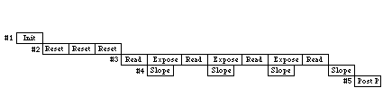
Figure 4.2.8-1 RAMP Exposure Sequence

4.6 Planning Command Pool File (PLCP Command Sets)

4.6.8 Mode Transition: HOLD to BOOT

Command Block:   NHLDBOO          Title:   HOLD to BOOT Mode Transition                       
Description:   Transition the instrument from the HOLD mode to the BOOT mode in preparation   
for imiging operations, or other activities requiring use of the embedded flight software.    
Constraints:   This command block should be initiated TBD minutes prior to the scheduled      
imiging sequence to allow for instrument configuration and warm-up.                           
                                Function                                    Time Required     
                                                                                (sec)         
  1  Enable NSSC-I CSCOMM (AP-21)                                          TBD                 
  2  Enable NSSC-I MACRO (AP-22)                                           TBD                 
  3  Close the LVPS Operate relay (Discrete Command: NEOPER1) to apply     TBD                 
     power to the: + support electronics section (SES) + control section                       
     (CS) boot + detector electronics section (DES) No commands to the                         
     software (MARs) can be sent until the CS boot activation and                              
     initialization sequence has completed. This process takes TBD                             
     seconds.                                                                                  
  4  Set CS EDAC processing parameters + enable auto correction for        TBD                 
     single bit errors (MAR: NENEDACC) + enable reset on multi-bit                             
     errors  (MAR: NENEDACM) + enable s/w refresh of EDAC RAM (MAR:                            
     NEDACSWR)                                                                                 
  5  Turn on CS limit checking using the NENLIMIT MAR. The CS boot         TBD                 
     flight software is activated with limit checking off.                                     
  6  Enable science data interface using TBD command                       TBD                 
  7  Disable Bus wait state using the NBUSWAIT MAR. The CS is              TBD                 
     initialized with one wait state added to the existing wait state(s)                       
     used for all processor bus traffic. This added wait state will be                         
     left enabled when memory access problems associated with radiation                        
     degradation occur. Until that time, the Bus wait state will be                            
     disabled after initialization to allow the fastest memory access                          
     time possible.                                                                            
  8  Enable A/D collection using the NENA2DC MAR to allow for the          TBD                 
     collection of analog telemetry data.                                                      
  9  Enable the Watch Dog Timer using the NENWDT MAR.                      TBD                 
 10                                                                                            
                               Total Time                                 TBD                 

4.6.11 PNCPYOPR

This flow chart shows the control flow imbeded in the PNCPYOPR PLCP command set listed in Section 7.0

5.0 MACRO ACTIVATION REQUEST DEFINITIONS

This section defines the NICMOS macros in terms of data content and uplink format. Table 5-1 shows the code level macros, and Table 5-2 shows the high level macros. Each macro has been assigned a unique activation number (OpCode) within the following catagories: Maintenance (0 - 63), Mechanisms (64 - 127), and Detector Operations (128 - 191). High level macros have been assigned OpCodes 192 - 255.

Table 5-1 NICMOS Code Level Macros

No.   Macro Activation Request     Name     OpCode  No.  Macro Activation Request      Name     OpCode  
5.12  Abort Current Macro        NABORTM    11/ibo  5.2  Enable EDAC Detection      NEEDACDT    28/nb   
      Processing                                      9                                                 
5.37  Abort Wait                 NABTWAIT   36/io   5.3  Enable Limits Monitoring   NELIMITS    29/ibo  
                                                      0                                                 
5.76  Start MIF Exposure         NACCUM(x)  134/no  5.2  Enable EDAC MultiBit       NEMRESET    22/nbo  
                                                      3  Error Reset                                    
5.13  Collect Analog             NALGDIAG   12/no   5.2  Enable EDAC Refresh        NEREFRSH    24/nbo  
      Diagnostic Data                                 5                                                 
5.86  Detector Auto Reset        NAUTO(x)   144/no  5.5  Move FOM to Absolute       NFOMABS     65/no   
                                                      1  Position                                       
5.78  Start Bright Object        NBRTOBJ(x  136/no  5.5  Move FOM to Relative       NFOMREL     64/no   
      Exposure                   )                    0  Position                                       
5.70  Operate Calibration Lamp   NCALAMP    128/no  5.8  Operate FPA Temperature    NFPATMP     145/no  
                                                      7  Sensor                                         
5.16  Compute Checksum           NCHKSUM    15/nbo  5.5  Move Filter Wheel to       NFWABS(x)   67/no   
                                                      3  Absolute Position                              
5.11  Clear All Queues           NCLEARQS   10/ibo  5.5  Move Filter Wheel to       NFWREL(x)   66/no   
                                                      2  Relative Position                              
 5.8  Restore Motor              NCOMREST    7/no   5.3  NO-OP Immediate            NIMMNOOP    38/ibo  
      Commutation                                     9                                                 
 5.6  Copy to EEPROM             NCPY2EE    5/nbo   5.8  Initialize Image/Header    NINITSD     140/no  
                                                      2  Buffers                                        
 5.7  Copy to RAM/EDAC RAM       NCPY2RAM   6/nbo   5.1  Jump to Operate            NJMP2OPR    17/nb   
      Memory                                          8                                                 
 5.9  Copy to TPG Memory         NCPY2TPG    8/no   5.5  Load CS Memory-Mapped I/O  NLDCS       4/nbo   
5.17  Reset to Boot              NCSRESET   16/ibo  5.4  Load DES Memory-Mapped     NLDDES       3/no   
                                                         I/O                                            
5.33  Disable A/D Collection     NDA2DENG   32/ib   5.1  Load EDAC RAM Variable     NLDEDAC     1/nbo   
5.28  Disable Bus Wait State     NDBWAIT    27/nb   5.2  Load EDAC RAM Fixed        NLDEDACF    41/nbo  
5.43  Disable CS Paging          NDCSPAGE   43/no   5.3  Load SES Memory-Mapped     NLDSES       2/no   
                                                         I/O                                            
5.35  Disable Watchdog Timer     NDDOGTIM   34/ibo  5.4  Install Memory Monitor     NMEMMON     40/nbo  
                                                      1                                                 
5.22  Disable EDAC Correction    NDEDACCR   21/nbo  5.7  Start Multi-Accum          NMULTI(x)   137/no  
                                                      9  Exposure                                       
5.20  Disable EDAC Detection     NDEDACDT   19/nbo  5.3  NO-OP Normal               NNORNOOP    37/nbo  
                                                      8                                                 
5.14  Collect Digital            NDIGDIAG   13/no   5.7  Operate Detector           NOPRVLT     133/no  
      Diagnostic Data                                 5  Voltages                                       
5.31  Disable Limits Monitoring  NDLIMITS   30/ibo  5.5  Move PAM Focus             NPAMFCS     69/no   
                                                      5                                                 
5.40  Dump Memory                NDMPMEM    39/nbo  5.5  Move PAM to Relative       NPAMTILT    68/no   
                                                      4  Position                                       
5.24  Disable EDAC multibit      NDMRESET   23/nbo  5.7  Start Ramp Exposure        NRAMP(x)    135/no  
      err. reset                                      7                                                 
5.26  Disable EDAC Refresh       NDREFRSH   25/nbo  5.4  Reset SD Dump Pointers     NRESTSD     44/no   
                                                      4                                                 
5.72  Set Detector Bandwidth     NDTBAND(x  130/no  5.1  Perform Self-test          NSELFTST    18/no   
                                 )                    9                                                 
5.71  Calibrate DES A2D          NDTCALIB   129/no  5.5  Set Heater Setpoint        NSETHEAT    70/no   
                                                      6                                                 
5.73  Set Detector Gains         NDTGAIN(x  131/no  5.7  Set Detector Voltage       NSETVLT     132/no  
                                 )                    4                                                 
5.81  Dump Image                 NDUMPSD    139/no  5.8  CSCOMM Slew Confirmation   NSLEWACK    141/io  
                                                      3                                                 
5.32  Enable A/D Collection      NEA2DENG   31/ib   5.8  Perform Target             NTARACQ     138/no  
                                                      0  Acquisition                                    
5.27  Enable Bus Wait State      NEBWAIT    26/nb   5.1  Time Code Update           NTCUPDTE    14/no   
                                                      5                                                 
5.42  Enable CS Paging           NECSPAGE   42/no   5.8  Take Data Flag Down        NTDFDOWN    142/io  
                                                      4                                                 
5.34  Enable Watchdog Timer      NEDOGTIM   33/ibo  5.8  Take Data Flag Up          NTDFUP      143/io  
                                                      5                                                 
5.21  Enable EDAC Correction     NEEDACCR   20/nbo  5.1  Collect TPG Memory         NTPG2RAM     9/no   
                                                      0                                                 
                                                    5.3  Wait                       NWAIT       35/no   
                                                      6                                                 

OpCode/n=normal, i=immediate, b=boot, o=operate

Table 5-2 NICMOS High Level Macros

                  Shell Macros                                      Program Macros                    
No.   Macro Activation Request    Name     OpCode  No.   Macro Activation Request      Name     OpCode  
5.10  Position the Filter       NFILTER(x   192    5.20  NACCUM on detector #1      NACCUM1S     238    
   0  Wheel                     )                     0  using the slow bandwidth                       
5.10  Position the FOM          NFOM        193    5.20  NACCUM on detector #1      NACCUM1F     239    
   1                                                  0  using the fast bandwidth                       
5.10  Load PROGID and OBSET     NPROGS1     194    5.20  NACCUM on detector #2      NACCUM2S     240    
   2  for detector number 1                           0  using the slow bandwidth                       
5.10  Load PROGID and OBSET     NPROGS2     195    5.20  NACCUM on detector #2      NACCUM2F     241    
   2  for detector number 2                           0  using the fast bandwidth                       
5.10  Load PROGID and OBSET     NPROGS3     196    5.20  NACCUM on detector #3      NACCUM3S     242    
   2  for detector number 3                           0  using the slow bandwidth                       
                                                   5.20  NACCUM on detector #3      NACCUM3F     243    
                                                      0  using the fast bandwidth                       
                                                   5.20  NRAMP on detector #1       NRAMP1S      244    
                                                      1  using the slow bandwidth                       
                                                   5.20  NRAMP on detector #1       NRAMP1F      245    
                                                      1  using the fast bandwidth                       
                                                   5.20  NRAMP on detector #2       NRAMP2S      246    
                                                      1  using the slow bandwidth                       
                                                   5.20  NRAMP on detector #2       NRAMP2F      247    
                                                      1  using the fast bandwidth                       
                                                   5.20  NRAMP on detector #3       NRAMP3S      248    
                                                      1  using the slow bandwidth                       
                                                   5.20  NRAMP on detector #3       NRAMP3F      249    
                                                      1  using the fast bandwidth                       
                                                   5.20  NMULTI on detector #1      NMULTI1S     250    
                                                      2  using the slow bandwidth                       
                                                   5.20  NMULTI on detector #1      NMULTI1F     251    
                                                      2  using the fast bandwidth                       
                                                   5.20  NMULTI on detector #2      NMULTI2S     252    
                                                      2  using the slow bandwidth                       
                                                   5.20  NMULTI on detector #2      NMULTI2F     253    
                                                      2  using the fast bandwidth                       
                                                   5.20  NMULTI on detector #3      NMULTI3S     254    
                                                      2  using the slow bandwidth                       
                                                   5.20  NMULTI on detector #3      NMULTI3F     255    
                                                      2  using the fast bandwidth                       


5.1 Load EDAC RAM Memory Variable

MAR Contents Definition

NLDEDAC               Load EDAC RAM memory with data from the ground. This       
                      macro supports a variable amount of words to load.         
                      Because a variable number of words can not be defined in   
                      the macro manager's macro table, this macro can not be     
                      used within high level macros unless the number of words   
                      to load is fixed in a unique tfpf.                         
Normal or Immediate   Normal                                                     
Valid Modes           Boot, Operate, Observe                                     
MAR Op code           01 (hex)                                                   
Data Type             unsigned integer                                           
                                Parameter Data                                   
       NWORDS         Number of words to load into EDAC RAM                      
       Units          16 bit words                                               
       Bounds         1 -  4,092 (limited by the size of the data FIFO [4096 -   
                      4 words])                                                  
     Data Type        unsigned integer                                           
Nominal Value         1                                                          
      DADDRESS        Destination address on the EDAC RAM board                  
Units                 Memory location (even address word boundary)               
Bounds                BOOT: 0 - 001E FFFF           OPERATE: 0 - 001F FFFF        
                                                    ([[Delta]] 2,097,151)         
Data Type             unsigned integer                                           
Nominal Value         NICLOADO                                                   
      DATA(x)         Words to Load. DATA1 goes into the location specified in   
                      DADDRESS                                                   
Units                 16 bit words                                               
Bounds                0 - FFFF (hex)                                             
Data Type             raw binary                                                 
Nominal Value         DATA1 = 0, DATA2 - DATA12 AAAA (hex)                       
     CSMODE (*)       Boot or Operate selector                                   
Units                 flag                                                       
Bounds                0 - 1 (0 = Operate,  1 = Boot)                             
Data Type             unsigned integer                                           
Nominal Value         0                                                          

NLDEDAC Uplink Format:

MSB LSB

18   17   16   15   14   13   12   11   10    9    8   7    6     5    4   3     2    1   
 0   0                                 NWORDS                               Word 1        
 0   0                       DADDRESS (high order word)                     Word 2        
 0   0                       DADDRESS (low order word)                      Word 3        
 0   0                               DATAnword                              Word 4        
 0   0                                 * * *                                              
 0   0                                 DATA1                                              
 0   1       Spare      *     Spare (zero              MAR Op Code              NWORDS+4    
          (zero fill)            fill)                                                      

5.2 Load EDAC RAM Memory Fixed

MAR Contents Definition

NLDEDACF              Load EDAC RAM memory with data from the ground. A          
                      maximum of 12  16 bit words can be loaded using this       
                      macro.                                                     
Normal or Immediate   Normal                                                     
Valid Modes           Boot, Operate, Observe                                     
MAR Op code           29 (hex)                                                   
Data Type             unsigned integer                                           
                                Parameter Data                                   
       NWORDS         Number of words used in the DATA buffer defined below.     
       Units          16 bit words                                               
       Bounds         1 -  12                                                    
     Data Type        unsigned integer                                           
Nominal Value         1                                                          
      DADDRESS        Destination address on the EDAC RAM board.                 
Units                 Memory location (even address word boundary)               
Bounds                BOOT: 0 - 001E FFFF           OPERATE: 0 - 001F FFFF        
                                                    ([[Delta]] 2,097,151)         
Data Type             unsigned integer                                           
Nominal Value         NICLOADO                                                   
        DATA          Words to Load. DATA1 goes into the location specified in   
                      DADDRESS. To load a 32 bit word with the hex value of      
                      '12345678' set DATA2 to '1234' and DATA1 to '5678'         
Units                 n/a                                                        
Bounds                0 - FFFF (hex)     AAAA (hex) = unused                     
Data Type             raw binary                                                 
Nominal Value         DATA1=0, DATA2-12=AAAA (hex)                               
     CSMODE (*)       Boot or Operate selector                                   
Units                 flag                                                       
Bounds                0 - 1 (0 = Operate,  1 = Boot)                             
Data Type             unsigned integer                                           
Nominal Value         0                                                          

NLDEDACF Uplink Format:

MSB LSB

18   17   16   15   14   13   12   11   10    9    8   7     6    5   4     3    2   1    
 0   0                   Spare (zero fill)                      NWORDS       Word 1        
 0   0                       DADDRESS (high order word)                     Word 2        
 0   0                       DADDRESS (low order word)                      Word 3        
 0   0                                 DATA12                               Word 4        
 0   0                                 DATA11                               Word 5        
 0   0                                 DATA10                               Word 6        
 0   0                                 DATA9                                Word 7        
 0   0                                 DATA8                                Word 8        
 0   0                                 DATA7                                Word 9        
 0   0                                 DATA6                                Word 10       
 0   0                                 DATA5                                Word 11       
 0   0                                 DATA4                                Word 12       
 0   0                                 DATA3                                Word 13       
 0   0                                 DATA2                                Word 14       
 0   0                                 DATA1                                Word 15       
 0   1       Spare      *     Spare (zero              MAR Op Code            Word 16       
          (zero fill)            fill)                                                      

5.3 Load SES Memory-Mapped I/O

MAR Contents Definition

NLDSES                Load the Support Electronics Section (SES) memory with     
                      data from the ground. This macro allows manipulation of    
                      the instrument functions controlled by the SES.  For       
                      more information on the functions and their required       
                      parameters, refer to NICMOS SER SW-083, ELECT-142,         
                      ELECT-151, and ELECT-131                                   
Normal or Immediate   Normal                                                     
Valid Modes           Operate, Observe                                           
MAR Op code           02 (hex)                                                   
Data Type             unsigned integer                                           
                                Parameter Data                                   
      FUNCTION        Software function identifier used to activate a software   
                      load routine. The index number shown below is the value    
                      for the FUNCTION parameter.                                
Units                 index (1 - 9 Motor Control #1 board, 10 - 24 Motor         
                      Control #2)                                                
Bounds                1 =                10 =               18 =                 
                      Ld_Motor_Latch 2   Ld_Motor_Latch_A   Ld_Motor_Latch_B     
                      = Ld_Cmd_Latch 3   11 =               19 =                 
                      =                  Ld_Cmd_Latch_A     Ld_Cmd_Latch_B 20    
                      Ld_Step_Counter    12 =               =                    
                      4 =                Ld_Step_Counter_A  Ld_Step_Counter_B    
                      Ld_Comm_Latch 5    13 =               21 =                 
                      = Ld_Phase_FW1 6   Ld_Comm_Latch_A    Ld_Comm_Latch_B 22   
                      = Ld_Phase_FOM_X   14 =               = Ld_Phase_FW3 23    
                      7 =                Ld_Phase_FW2 15    =                    
                      Ld_Phase_FOM_Y 8   = Ld_Phase_PAM_X   Ld_Phase_PAM_Focus   
                      =                  16 =               24 =                 
                      Ld_CAL_Lamp_Latch  Ld_Phase_PAM_Y     Set_Comm_Clock_B     
                      9 =                17 =               25 = Ld_TC_Cmd 26    
                      Set_Comm_Clock     Set_Comm_Clock_A   = Ld_TC_Enable 27    
                                                            = Ld_Setpoint 28 =   
                                                            Ld_SES_Adrs_FIFO     
                                                            29 =                 
                                                            Reset_Data_FIFO 30   
                                                            = Ld_TC_Clock        
Data Type             unsigned integer                                           
Nominal Value         8                                                          
     DATA1 - 5        Data buffer (five 16 bit words). These words will          
                      contain information required by FUNCTION above. The        
                      following pages (sections 5.3.1 - 5.3.29) define the       
                      contents of the FUNCTION parameters.                       
Units                 n/a                                                        
Bounds                0 - FFFF                                                   
Data Type             raw binary                                                 
Nominal Value         DATA1 = 1, DATA2 = 0, DATA3 - DATA5 = AAAA (hex)           

NLDSES Uplink Format:

MSB LSB

18   17   16   15   14   13   12   11   10    9    8   7    6     5    4   3     2    1   
 0   0               Spare (zero fill)                    FUNCTION          Word 1        
 0   0                                 DATA1                                Word 2        
 0   0                                 DATA2                                Word 3        
 0   0                                 DATA3                                Word 4        
 0   0                                 DATA4                                Word 5        
 0   0                                 DATA5                                Word 6        
 0   1       Spare      0     Spare (zero              MAR Op Code            Word 7        
          (zero fill)            fill)                                                      

Load SES Memory-Mapped I/O continued

5.3.1 Load Motor Latch

FUNCTION              Set the motor step rate for one of the three motors        
Ld_Motor_Latch        controlled by this board.  This function will also cause   
                      a motor holdoff count to be loaded into the motor latch    
                      by the CS flight software. The holdoff count is stored     
                      in a table in EDAC memory.  The holdoff count defines      
                      the length of time to keep the selected motor enabled      
                      after completion of a motor movement. This value will be   
                      set during initial testing and is not expected to          
                      change.                                                    
Function Code         1                                                          
Motor Control Board   controlling the Filter Wheel #1,  FOM X-Tilt, and the      
#1                    FOM Y-Tilt                                                 
                                Parameter Data                                   
       DATA1          Step rate (motor speed)                                    
Units                 index                                                      
Bounds                4 - 7: 4 = motor speed: 30.52 pps 5 = motor speed: 40.69   
                      pps 6 = motor speed: 61.04 pps 7 = motor speed: 122.07     
                      pps                                                        
Data Type             unsigned integer                                           
Nominal Value         7                                                          
       DATA2          Mechanism Number                                           
Units                 index                                                      
Bounds                0,3,4 0 = Filter Wheel #1 3 = FOM X-Tilt 4 = FOM Y-Tilt    
Data Type             unsigned integer                                           
Nominal Value         0                                                          

Load SES Memory-Mapped I/O continued

5.3.2 Load Command Latch

FUNCTION              Load the Command Latch with the motor selection and        
Ld_Cmd_Latch          direction values, and load the Current Control Latch A     
                      with the motor current level. This function also loads     
                      the motor stall bits which are defined as table values     
                      in the flight software. The normal value for the stall     
                      bits are 0 (disabled).                                     
Function Code         2                                                          
Motor Control Board   controlling the Filter Wheel #1,  FOM X-Tilt, and the      
#1                    FOM Y-Tilt                                                 
                                Parameter Data                                   
       DATA1          Motor direction                                            
Units                 index                                                      
Bounds                0 = counter clockwise direction (negative) 1 = clockwise   
                      rotation (positive)                                        
Data Type             unsigned integer                                           
Nominal Value         0                                                          
       DATA2          Motor select Select none or one of the three mechanisms    
                      (FW1, FOM X-Tilt, or FOM Y-Tilt). When a motor is          
                      selected, decode logic enables the appropriate motor       
                      driver chip and the appropriate motor commutation          
                      circuitry. Before a motor can be stepped that motor's      
                      communtation circuitry must be enabled (selected). Also    
                      see Set_Comm_Clock (5.3.9).                                
Units                 index                                                      
Bounds                0 = none 1 = FOM X-Tilt 2 = Filter Wheel #1 3 = FOM        
                      Y-Tilt                                                     
Data Type             unsigned integer                                           
Nominal Value         0                                                          
       DATA3          Motor drive current level                                  
Units                 index                                                      
Bounds                0 = disable driver 1 = 19% 2 = 60% 3 = 100%                
Data Type             unsigned integer                                           
Nominal Value         0                                                          

Load SES Memory-Mapped I/O continued

5.3.3 Load Step Counter

FUNCTION              Load the Step Counter Latch with the number of motor       
Ld_Step_Counter       steps required (relative to the current motor position).   
                      Note: The hardware step controller design generates one    
                      extra step beyond the specified parameter value defined    
                      in DATA1 below.                                            
Function Code         3                                                          
Motor Control Board   controlling the Filter Wheel #1,  FOM X-Tilt, and the      
#1                    FOM Y-Tilt                                                 
                                Parameter Data                                   
       DATA1          Number of motor steps                                      
Units                 steps                                                      
Bounds                0 - 65535 Note: No mechanism specific range checking is    
                      provided with this function. If the number of steps        
                      selected is beyond the range of the mechanism soft         
                      stops, the instrument will safe or suspend. See Section    
                      6 for more information on mechanism soft stops.            
Data Type             unsigned integer                                           
Nominal Value         1                                                          

5.3.4 Load Commutation Latch

FUNCTION              Load the motor commutations, for each of the three         
Ld_Comm_Latch         mechanism motors on this control board, from EDAC memory   
                      into the Motor Phase Latch.  Motor commutations are the    
                      motor's bipolar starting phase (it's position within       
                      it's field of motion). After the starting phases have      
                      been loaded, they need to be transfered to the             
                      appropriate mechanism using one of the three Ld_Phase_x    
                      commands. Normally motor commutations are retained for     
                      each mechanism automatically by the Dual Phase Drive       
                      Logic. However, commutations will need to be loaded        
                      after a power-on-reset using this function or the          
                      NCOMREST macro activation request.                         
Function Code         4                                                          
Motor Control Board   controlling the Filter Wheel #1,  FOM X-Tilt, and the      
#1                    FOM Y-Tilt                                                 
                                Parameter Data                                   
       DATA1          Filter Wheel #1 commutation phasing for the A and B        
                      windings                                                   
Units                 index                                                      
Bounds                0 = A-winding:      0 deg.,  B-winding:      0 deg. 1 =    
                      A-winding:      0 deg.,  B-winding:  180 deg. 2 =          
                      A-winding:  180 deg.,  B-winding:      0 deg. 3 =          
                      A-winding:  180 deg.,  B-winding:  180 deg.                
Data Type             unsigned integer                                           
Nominal Value         0                                                          
       DATA2          FOM X-Tilt commutation phasing for the A and B windings    
Units                 index                                                      
Bounds                0 - 3 (same as DATA1)                                      
Data Type             unsigned integer                                           
Nominal Value         0                                                          
       DATA3          FOM Y-Tilt commutation phasing for the A and B windings    
Units                 index                                                      
Bounds                0 - 3 (same as DATA1)                                      
Data Type             unsigned integer                                           
Nominal Value         0                                                          

Load SES Memory-Mapped I/O continued

5.3.5 Load Phase Filter Wheel 1

FUNCTION              Transfers the Filter Wheel #1 motor phasing (commutation   
Ld_Phase_FW1          values) from the Motor Phase Latch into the FW1 Dual       
                      Phase Drive Logic commutation circuitry. This is the       
                      second step required to load the commutation values into   
                      the Filter Wheel motor.                                    
Function Code         5                                                          
Motor Control Board   controlling the Filter Wheel #1,  FOM X-Tilt, and the      
#1                    FOM Y-Tilt                                                 
                                Parameter Data                                   
       DATA1          No parameter data required                                 
Units                 n/a                                                        
Bounds                n/a                                                        
Data Type             n/a                                                        
Nominal Value         n/a                                                        

5.3.6 Load Phase FOM X

FUNCTION               Transfers the FOM X-Tilt motor phasing (commutation       
Ld_Phase_FOM_X         values) from the Motor Phase Latch into the FOM X Dual    
                       Phase Drive Logic commutation circuitry.                  
Function Code         6                                                          
Motor Control Board   controlling the Filter Wheel #1,  FOM X-Tilt, and the      
#1                    FOM Y-Tilt                                                 
                                Parameter Data                                   
       DATA1          No parameter data required                                 
Units                 n/a                                                        
Bounds                n/a                                                        
Data Type             n/a                                                        
Nominal Value         n/a                                                        

5.3.7 Load Phase FOM Y

FUNCTION               Transfers the FOM Y-Tilt motor phasing (commutation       
Ld_Phase_FOM_Y         values) from the Motor Phase Latch into the FOM Y Dual    
                       Phase Drive Logic commutation circuitry.                  
Function Code         7                                                          
Motor Control Board   controlling the Filter Wheel #1,  FOM X-Tilt, and the      
#1                    FOM Y-Tilt                                                 
                                Parameter Data                                   
       DATA1          No parameter data required                                 
Units                 n/a                                                        
Bounds                n/a                                                        
Data Type             n/a                                                        
Nominal Value         n/a                                                        

Load SES Memory-Mapped I/O continued

5.3.8 Load Calibration Lamp Latch

FUNCTION Ld_CAL_Lamp_Latch  Loads the three calibration lamp ON-OFF commands     
                            into the Cal Lamp Select Latch.  During normal       
                            operations, only one cal lamp will be on at a        
                            time. However, using this function there is          
                            nothing which prevents the user from turning on      
                            more than one cal lamp at a time.                    
Function Code         8                                                          
Motor Control Board   controlling the Filter Wheel #1,  FOM X-Tilt, and the      
#1                    FOM Y-Tilt                                                 
                                Parameter Data                                   
       DATA1          ON-OFF lamp selector                                       
Units                 16 bit memory map                                          
Bounds                0 - 380 (hex) Bit position 0 - 7 not used Bit position     
                      (0 relative) 8 ==> Lamp #1 (0 = OFF, 1 = ON) Bit           
                      position (0 relative) 9 ==> Lamp #2 (0 = OFF, 1 = ON)      
                      Bit position (0 relative) 10 => Lamp #3 (0 = OFF, 1 =      
                      ON) Bit position 11 - 15 not used                          
Data Type             unsigned integer                                           
Nominal Value         0                                                          

5.3.9 Set Commutation Clock

FUNCTION              Enable or disable the motor commutation clock and start    
Set_Comm_Clock        or stop the motor step counter for the selected motor.     
                      This is the 'Go' and 'Stop' button for the mechanism       
                      which was selected using the Ld_Cmd_Latch Function.        
                      Although this operation is part of the Ld_Cmd_Latch        
                      hardware function, a separate CS flight software           
                      function was created for both safety reasons and           
                      operational functionality.                                 
Function Code         9                                                          
Motor Control Board   controlling the Filter Wheel #1,  FOM X-Tilt, and the      
#1                    FOM Y-Tilt                                                 
                                Parameter Data                                   
       DATA1          Start stop selector                                        
Units                 index                                                      
Bounds                0 - 1: 0 = disable or stop mechanism movement,   1 =       
                      enable or start mechanism movement                         
Data Type             unsigned integer                                           
Nominal Value         0                                                          

Load SES Memory-Mapped I/O continued

5.3.10 Load Motor Latch A

FUNCTION                Set the motor step rate for one of the three motors      
Ld_Motor_Latch_A        controlled by Controller A on Motor Control Board #2.    
                        This function will also cause a motor holdoff count to   
                        be loaded into the motor latch by the CS flight          
                        software. The holdoff count is stored in a table in      
                        EDAC memory.  The holdoff count defines the length of    
                        time to keep the selected motor enabled after            
                        completion of a motor movement. This value will be set   
                        during initial testing and is not expected to change.    
Function Code         10                                                         
Motor Control Board   Controller A: Filter Wheel #2,  PAM X-Tilt, and the PAM    
#2                    Y-Tilt                                                     
                                Parameter Data                                   
       DATA1          Step rate (motor speed)                                    
Units                 index                                                      
Bounds                0 - 7: 0 = motor speed: 07.63 pps 1 = motor speed: 10.17   
                      pps 2 = motor speed: 15.26 pps 3 = motor speed: 30.52      
                      pps 4 = motor speed: 30.52 pps 5 = motor speed: 40.69      
                      pps 6 = motor speed: 61.04 pps 7 = motor speed: 122.07     
                      pps Note: The PAM motors should use the slower step        
                      rates (0 - 3) and the Filter Wheel should use the faster   
                      step rates (4 - 7) above.                                  
Data Type             unsigned integer                                           
Nominal Value         3                                                          
       DATA2          Mechanism Number                                           
Units                 index                                                      
Bounds                1,5,6 1 = Filter Wheel #2 5 = PAM X-Tilt 6 = PAM Y-Tilt    
Data Type             unsigned integer                                           
Nominal Value         1                                                          

Load SES Memory-Mapped I/O continued

5.3.11 Load Command Latch A

FUNCTION               Load the Command Latch with the motor selection and       
Ld_Cmd_Latch_A         direction values, and load the Current Control Latch A    
                       with the motor current level. This function also loads    
                       the motor stall bits which are defined as table values    
                       in the flight software. The normal value for the stall    
                       bits are 0 (disabled).                                    
Function Code         11                                                         
Motor Control Board   Controller A: Filter Wheel #2,  PAM X-Tilt, and the PAM    
#2                    Y-Tilt                                                     
                                Parameter Data                                   
       DATA1          Motor direction                                            
Units                 index                                                      
Bounds                0 = counter clockwise direction (negative) 1 = clockwise   
                      rotation (positive)                                        
Data Type             unsigned integer                                           
Nominal Value         0                                                          
       DATA2          Motor select Select none or one of the three mechanisms.   
                      When a motor is selected, decode logic enables the         
                      appropriate motor driver chip and the appropriate motor    
                      commutation circuitry. Before a motor can be stepped       
                      that motor's communtation circuitry must be enabled        
                      (selected). Also see Set_Comm_Clock_A (5.3.24).            
Units                 index                                                      
Bounds                0 = none 1 = PAM X-Tilt 2 = Filter Wheel #2 3 = PAM        
                      Y-Tilt                                                     
Data Type             unsigned integer                                           
Nominal Value         0                                                          
       DATA3          Motor drive current level                                  
Units                 index                                                      
Bounds                0 = disable driver 1 = 19% 2 = 60% 3 = 100%                
Data Type             unsigned integer                                           
Nominal Value         0                                                          

Load SES Memory-Mapped I/O continued

5.3.12 Load Step Counter A

FUNCTION                 Load the Step Counter Latch with the number of motor    
Ld_Step_Counter_A        steps required (relative to the current motor           
                         position). Note: The hardware step controller design    
                         generates one extra step beyond the specified           
                         parameter value defined in DATA1 below.                 
Function Code         12                                                         
Motor Control Board   Controller A: Filter Wheel #2,  PAM X-Tilt, and the PAM    
#2                    Y-Tilt                                                     
                                Parameter Data                                   
       DATA1          Number of motor steps                                      
Units                 index                                                      
Bounds                0 - 65535 Note: No mechanism specific range checking is    
                      provided with this function. If the number of steps        
                      selected is beyond the range of the mechanism soft         
                      stops, the instrument will safe or susspend. See Section   
                      6 for more information on mechanism soft stops.            
Data Type             unsigned integer                                           
Nominal Value         1                                                          

5.3.13 Load Commutation Latch A

FUNCTION                 Load the motor commutations, for each of the three      
Ld_Comm_Latch_A          mechanism motors on this control board, from EDAC       
                         memory into the Motor Phase Latch.  Motor               
                         commutations are the motor's bipolar starting phase     
                         (it's position within it's field of motion). After      
                         the starting phases have been loaded, they need to be   
                         transfered to the appropriate mechanism using one of    
                         the three Ld_Phase_x commands. Normally motor           
                         commutations are retained for each mechanism            
                         automatically by the Dual Phase Drive Logic. However,   
                         commutations will need to be loaded after a             
                         power-on-reset using this function or the NCOMREST      
                         macro activation request.                               
Function Code         13                                                         
Motor Control Board   Controller A: Filter Wheel #2,  PAM X-Tilt, and the PAM    
#2                    Y-Tilt                                                     
                                Parameter Data                                   
       DATA1          Filter Wheel #2 commutation phasing for the A and B        
                      windings                                                   
Units                 index                                                      
Bounds                0 = A-winding:      0 deg.,  B-winding:      0 deg. 1 =    
                      A-winding:      0 deg.,  B-winding:  180 deg. 2 =          
                      A-winding:  180 deg.,  B-winding:      0 deg. 3 =          
                      A-winding:  180 deg.,  B-winding:  180 deg.                
Data Type             unsigned integer                                           
Nominal Value         0                                                          
       DATA2          PAM X-Tilt commutation phasing for the A and B windings    
Units                 index                                                      
Bounds                0 - 3 (same as DATA1)                                      
Data Type             unsigned integer                                           
Nominal Value         0                                                          
       DATA3          PAM Y-Tilt commutation phasing for the A and B windings    
Units                 index                                                      
Bounds                0 - 3 (same as DATA1)                                      
Data Type             unsigned integer                                           
Nominal Value         0                                                          

Load SES Memory-Mapped I/O continued

5.3.14 Load Phase Filter Wheel 2

FUNCTION              Transfers the Filter Wheel #2 motor phasing (commutation   
Ld_Phase_FW2          values) from the Motor Phase Latch into the FW2 Dual       
                      Phase Drive Logic commutation circuitry. This is the       
                      second step required to load the commutation values into   
                      the Filter Wheel motor.                                    
Function Code         14                                                         
Motor Control Board   Controller A: Filter Wheel #2,  PAM X-Tilt, and the PAM    
#2                    Y-Tilt                                                     
                                Parameter Data                                   
       DATA1          No parameter data required                                 
Units                 n/a                                                        
Bounds                n/a                                                        
Data Type             n/a                                                        
Nominal Value         n/a                                                        

5.3.15 Load Phase PAM X

FUNCTION                Transfers the PAM X-Tilt motor phasing (commutation      
Ld_Phase_PAM_X          values) from the Motor Phase Latch into the PAM X Dual   
                        Phase Drive Logic commutation circuitry.                 
Function Code         15                                                         
Motor Control Board   Controller A: Filter Wheel #2,  PAM X-Tilt, and the PAM    
#2                    Y-Tilt                                                     
                                Parameter Data                                   
       DATA1          No parameter data required                                 
Units                 n/a                                                        
Bounds                n/a                                                        
Data Type             n/a                                                        
Nominal Value         n/a                                                        

5.3.16 Load Phase PAM Y

FUNCTION                Transfers the PAM Y-Tilt motor phasing (commutation      
Ld_Phase_PAM_Y          values) from the Motor Phase Latch into the PAM Y Dual   
                        Phase Drive Logic commutation circuitry.                 
Function Code         16                                                         
Motor Control Board   Controller A: Filter Wheel #2,  PAM X-Tilt, and the PAM    
#2                    Y-Tilt                                                     
                                Parameter Data                                   
       DATA1          No parameter data required                                 
Units                 n/a                                                        
Bounds                n/a                                                        
Data Type             n/a                                                        
Nominal Value         n/a                                                        

Load SES Memory-Mapped I/O continued

5.3.17 Set Commutation Clock A

FUNCTION                 Enable or disable the motor commutation clock and       
Set_Comm_Clock_A         start or stop the motor step counter for the selected   
                         motor. This is the 'Go' and 'Stop' button for the       
                         mechanism which was selected previously using the       
                         Ld_Cmd_Latch_A Function. Although this operation is     
                         part of the Ld_Cmd_Latch hardware function, a           
                         separate CS flight software function was created for    
                         both safety reasons and operational functionality.      
Function Code         17                                                         
Motor Control Board   Controller A: Filter Wheel #2,  PAM X-Tilt, and the PAM    
#2                    Y-Tilt                                                     
                                Parameter Data                                   
       DATA1          Start stop selector                                        
Units                 index                                                      
Bounds                0 - 1: 0 = disable or stop mechanism movement,   1 =       
                      enable or start mechanism movement                         
Data Type             unsigned integer                                           
Nominal Value         0                                                          

Load SES Memory-Mapped I/O continued

5.3.18 Load Motor Latch B

FUNCTION                Set the motor step rate for one of the three motors      
Ld_Motor_Latch_B        controlled by Controller B on Motor Control Board #2.    
                        This function will also cause a motor holdoff count to   
                        be loaded into the motor latch by the CS flight          
                        software. The holdoff count is stored in a table in      
                        EDAC memory.  The holdoff count defines the length of    
                        time to keep the selected motor enabled after            
                        completion of a motor movement. This value will be set   
                        during initial testing and is not expected to change.    
Function Code         18                                                         
Motor Control Board   Controller B: Filter Wheel #3,  PAM Focus                  
#2                                                                               
                                Parameter Data                                   
       DATA1          Step rate (motor speed)                                    
Units                 index                                                      
Bounds                0 - 7: 0 = motor speed: 07.63 pps 1 = motor speed: 10.17   
                      pps 2 = motor speed: 15.26 pps 3 = motor speed: 30.52      
                      pps 4 = motor speed: 30.52 pps 5 = motor speed: 40.69      
                      pps 6 = motor speed: 61.04 pps 7 = motor speed: 122.07     
                      pps Note: The PAM motors should use the first four         
                      (slower) step rates and the Filter Wheel should use the    
                      faster four (4 - 7) step rates.                            
Data Type             unsigned integer                                           
Nominal Value         3                                                          
       DATA2          Mechanism Number                                           
Units                 index                                                      
Bounds                2,7 2 = Filter Wheel #3 7 = PAM Focus                      
Data Type             unsigned integer                                           
Nominal Value         2                                                          

Load SES Memory-Mapped I/O continued

5.3.19 Load Command Latch B

FUNCTION                Load the Command Latch with the motor selection and      
Ld_Cmd_Latch_B          direction values, and load the Current Control Latch B   
                        with the motor current level. This function also loads   
                        the motor stall bits which are defined as table values   
                        in the flight software. The normal value for the stall   
                        bits are0 (disabled).                                    
Function Code         19                                                         
Motor Control Board   Controller B: Filter Wheel #3,  PAM Focus                  
                                Parameter Data                                   
       DATA1          Motor direction                                            
Units                 index                                                      
Bounds                0 = counter clockwise direction (negative) 1 = clockwise   
                      rotation (positive)                                        
Data Type             unsigned integer                                           
Nominal Value         0                                                          
       DATA2          Motor select Select none or one of the three mechanisms.   
                      When a motor is selected, decode logic enables the         
                      appropriate motor driver chip and the appropriate motor    
                      commutation circuitry. Before a motor can be stepped       
                      that motor's communtation circuitry must be enabled        
                      (selected). Also see Set_Comm_Clock_B (5.3.17).            
Units                 index                                                      
Bounds                0 = none 1 = PAM Focus 2 = Filter Wheel #3 3 = none        
Data Type             unsigned integer                                           
Nominal Value         0                                                          
       DATA3          Motor drive current level                                  
Units                 index                                                      
Bounds                0 = disable driver 1 = 19% 2 = 60% 3 = 100%                
Data Type             unsigned integer                                           
Nominal Value         0                                                          

Load SES Memory-Mapped I/O continued

5.3.20 Load Step Counter B

FUNCTION                 Load the Step Counter Latch with the number of motor    
Ld_Step_Counter_B        steps required (relative to the current motor           
                         position). Note: The hardware step controller design    
                         generates one extra step beyond the specified           
                         parameter value defined in DATA1 below.                 
Function Code         20                                                         
Motor Control Board   Controller B: Filter Wheel #3,  PAM Focus                  
                                Parameter Data                                   
       DATA1          Number of motor steps                                      
Units                 index                                                      
Bounds                0 - 65535 Note: No mechanism specific range checking is    
                      provided with this function. If the number of steps        
                      selected is beyond the range of the mechanism soft         
                      stops, the instrument will safe or susspend. See Section   
                      6 for more information on mechanism soft stops.            
Data Type             unsigned integer                                           
Nominal Value         1                                                          

5.3.21 Load Commutation Latch B

FUNCTION                 Load the motor commutations, for each of the three      
Ld_Comm_Latch_B          mechanism motors on this control board, from EDAC       
                         memory into the Motor Phase Latch.  Motor               
                         commutations are the motor's bipolar starting phase     
                         (it's position within it's field of motion). After      
                         the starting phases have been loaded, they need to be   
                         transfered to the appropriate mechanism using one of    
                         the three Ld_Phase_x commands. Normally motor           
                         commutations are retained for each mechanism            
                         automatically by the Dual Phase Drive Logic. However,   
                         commutations will need to be loaded after a             
                         power-on-reset using this function or the NCOMREST      
                         macro activation request.                               
Function Code         21                                                         
Motor Control Board   Controller B: Filter Wheel #3,  PAM Focus                  
                                Parameter Data                                   
       DATA1          Filter Wheel #3 commutation phasing for the A and B        
                      windings                                                   
Units                 index                                                      
Bounds                0 = A-winding:      0 deg.,  B-winding:      0 deg. 1 =    
                      A-winding:      0 deg.,  B-winding:  180 deg. 2 =          
                      A-winding:  180 deg.,  B-winding:      0 deg. 3 =          
                      A-winding:  180 deg.,  B-winding:  180 deg.                
Data Type             unsigned integer                                           
Nominal Value         0                                                          
       DATA2          PAM Focus commutation phasing for the A and B windings     
Units                 index                                                      
Bounds                0 - 3 (same as DATA1)                                      
Data Type             unsigned integer                                           
Nominal Value         0                                                          

Load SES Memory-Mapped I/O continued

5.3.22 Load Phase Filter Wheel 3

FUNCTION              Transfers the Filter Wheel #3 motor phasing (commutation   
Ld_Phase_FW3          values) from the Motor Phase Latch into the FW3 Dual       
                      Phase Drive Logic commutation circuitry. This is the       
                      second step required to load the commutation values into   
                      the Filter Wheel motor.                                    
Function Code         22                                                         
Motor Control Board   Controller B: Filter Wheel #3,  PAM Focus                  
                                Parameter Data                                   
       DATA1          No parameter data required                                 
Units                 n/a                                                        
Bounds                n/a                                                        
Data Type             n/a                                                        
Nominal Value         n/a                                                        

5.3.23 Load Phase PAM Focus

FUNCTION                    Transfers the PAM Focus motor phasing (commutation   
Ld_Phase_PAM_Focus          values) from the Motor Phase Latch into the PAM X    
                            Dual Phase Drive Logic commutation circuitry.        
Function Code         23                                                         
Motor Control Board   Controller B: Filter Wheel #3,  PAM Focus                  
                                Parameter Data                                   
       DATA1          No parameter data required                                 
Units                 n/a                                                        
Bounds                n/a                                                        
Data Type             n/a                                                        
Nominal Value         n/a                                                        

5.3.24 Set Commutation Clock B

FUNCTION                 Enable or disable the motor commutation clock and       
Set_Comm_Clock_B         start or stop the motor step counter for the selected   
                         motor. This is the 'Go' and 'Stop' button for the       
                         mechanism which was selected previously using the       
                         Ld_Cmd_Latch_B Function. Although this operation is     
                         part of the Ld_Cmd_Latch hardware function, a           
                         separate CS flight software function was created for    
                         both safety reasons and operational functionality.      
Function Code         24                                                         
Motor Control Board   Controller B: Filter Wheel #3,  PAM Focus                  
                                Parameter Data                                   
       DATA1          Start stop selector                                        
Units                 n/a                                                        
Bounds                0 - 1: 0 = disable or stop mechanism movement,   1 =       
                      enable or start mechanism movement                         
Data Type             unsigned integer                                           
Nominal Value         0                                                          

Load SES Memory-Mapped I/O continued

5.3.25 Load Thermal Controller Command

FUNCTION Ld_TC_Cmd    This function controlls the AC299 8 bit shift/storage      
                      register used in loading the digital setpoint for the      
                      instrument heaters. Refer to NICMOS SER ELECT-131 Rev B    
                      prior to using any of the thermal controller functions     
                      (Ld_TC_Cmd, TC_Enable, Ld_Setpoint, and Ld_TC_Clock        
Function Code         25                                                         
SES Control Board     Data Acquisition Board                                     
                                Parameter Data                                   
       DATA1          Bitmap with the following characteristics:                 
Units                 n/a                                                        
Bounds                Bits 0 - 8 ==> not used Bits 9,10 register mode select:    
                      00 (bin) = do nothing (interface not in use)    01 (bin)   
                      = configures the register for shift out operation    11    
                      (bin) = configures the register for loading the setpoint   
                      value (via the Ld_Setpoint function) Bit 11    0 = do      
                      nothing    1 = latches the setpoint data word into the     
                      thermal controller setpoint latch Bit 12    0 = disable    
                      the clock gate to the shift register    1 = enable the     
                      clock gate to the shift register.  Bit 13,14,15 ==> not    
                      used                                                       
Data Type             unsigned integer                                           
Nominal Value         0                                                          

5.3.26 Load Thermal Controller Enable

FUNCTION              Enable or disable the serial data bus and serial clock     
Ld_TC_Enable          which connect the AC299 shift register to the thermal      
                      controller. When enabled, data and clock pulses can be     
                      sent to the thermal controller. Refer to NICMOS SER        
                      ELECT-131 Rev B prior to using any of the thermal          
                      controller functions (Ld_TC_Cmd, Ld_TC_Enable, and         
                      Ld_Setpoint)                                               
Function Code         26                                                         
Motor Control Board   Data Acquisition Board                                     
                                Parameter Data                                   
       DATA1          Enable / disable flag                                      
Units                 index                                                      
Bounds                0 -1  (0 = Data and clock disabled,  1 = Data and clock    
                      enabled)                                                   
Data Type             unsigned integer                                           
Nominal Value         0                                                          

Load SES Memory-Mapped I/O continued

5.3.27 Load Setpoint

FUNCTION Ld_Setpoint  Load the AC299 shift register with the 8-bit digital       
                      setpoint.  Refer to NICMOS SER ELECT-131 Rev B prior to    
                      using any of the thermal controller functions              
                      (Ld_TC_Cmd, TC_Enable, and Ld_Setpoint)                    
Function Code         27                                                         
Motor Control Board   Data Acquisition Board                                     
                                Parameter Data                                   
       DATA1          Setpoint                                                   
Units                 heater counts  (see MAR:  NSETHEAT)                        
Bounds                4 - 213                                                    
Data Type             unsigned integer                                           
Nominal Value         90                                                         

5.3.28 Load SES Address FIFO

FUNCTION                 Loads a multiplexer address of an analog telemetry      
Ld_SES_Adrs_FIFO         item onto the address FIFO on the data acquisition      
                         board. This is a 'one-shot' version of the NALGDIAG     
                         MAR. Also see the data acquisition board SER:           
                         ELECT-162 for more information.                         
Function Code         28                                                         
Motor Control Board   Data Acquisition Board                                     
                                Parameter Data                                   
       DATA1          Multiplexer address. The address is nine bits in length.   
                      Bit 0 is the least significant bit of the address, and     
                      bit 8 is the most significant bit. Bit 9 through bit 15    
                      are not used. Refer to appendix A of SER ELECT-162 for a   
                      description of the addresses.                              
Units                 Multiplexer location                                       
Bounds                0 - 018F (hex)                                             
Data Type             unsigned integer                                           
Nominal Value         0                                                          

5.3.29 Reset Data FIFO

FUNCTION              Reset the address FIFO on the data acquisition board.      
Reset_Data_FIFO       See NICMOS SER ELECT-162 for more information on the use   
                      of the data acquisition board.                             
Function Code         29                                                         
Motor Control Board   Data Acquisition Board                                     
                                Parameter Data                                   
       DATA1          No parameters are required for this function               
Units                 n/a                                                        
Bounds                n/a                                                        
Data Type             n/a                                                        
Nominal Value         n/a                                                        

5.3.30 Load Thermal Controller Clock

FUNCTION Ld_TC_Clock  Controlls the clocking of the SetPoint value to the        
                      Thermal Controller.  The 8-bit SetPoint value is loaded    
                      into the shift register on the SES board using the         
                      Ld_Setpoint SES function. Each call to the Ld_TC_Clock     
                      function sets the clock signal hi and then low again to    
                      produce a clock pulse. It must be called 8 times to        
                      transfer the entire SetPoint value.                        
Function Code         30                                                         
Motor Control Board   SES Board #3                                               
                                Parameter Data                                   
       DATA1          No parameters are required for this function               
Units                 n/a                                                        
Bounds                n/a                                                        
Data Type             n/a                                                        
Nominal Value         n/a                                                        

5.4 Load DES Memory-Mapped I/O

MAR Contents Definition

NLDDES                Load DES memory mapped I/O registers on the                
                      Communications board with data from the ground. The        
                      FUNCTION parameter defined below, controls which           
                      register is to be written to. Two registers are            
                      supported by this macro, the Command register  and the     
                      Control register.   Refer to NICMOS SER ELECT-172 for a    
                      description on the use of these registers.                 
Normal or Immediate   Normal                                                     
Valid Modes           Operate, Observe                                           
MAR Op code           03 (hex)                                                   
Data Type             unsigned integer                                           
                                Parameter Data                                   
      FUNCTION        Register select and command code.                          
       Units                                                                     
       Bounds         00 - F0 (hex) (function codes for the Command register)    
                      FF (hex) (selector for the Control register) Note: when    
                      using FUNCTION 50 (setting the DAC's) you must first       
                      enable the DAC's using FUNCTION 10 and then disable the    
                      DAC's when your done                                       
     Data Type        unsigned integer                                           
Nominal Value         00 (hex)                                                   
        DATA          24 bit data word to be loaded into the selected memory     
                      mapped register.                                           
Units                 n/a                                                        
Bounds                0 - FFFF FF                                                
Data Type             unsigned integer                                           
Nominal Value         00 (hex)                                                   
        TPG           TPG number (corresponding to a detector number). This      
                      parameter is required when loading the Command register.   
Units                 index                                                      
Bounds                1 - 3                                                      
Data Type             unsigned integer                                           
Nominal Value         1                                                          

NLDDES Uplink Format:

MSB LSB

18   17   16   15   14   13   12   11   10    9    8   7    6     5    4   3     2    1   
 0   0               FUNCTION                    DATA  (high order)         Word 1        
 0   0                           DATA  (low order)                          Word 2        
 0   0                       Spare (zero fill)                        TPG    Word 3        
 0   1       Spare      0     Spare (zero              MAR Op Code            Word 4        
          (zero fill)            fill)                                                      

5.5 Load CS Memory-Mapped I/O

MAR Contents Definition

NLDCS                 Load CS memory (CPU board and Communications board) with   
                      data from the ground. Refer to NICMOS SER SW-62 for        
                      information on loading CS memory.                          
Normal or Immediate   Normal                                                     
Valid Modes           Boot, Operate, Observe                                     
MAR Op code           04 (hex)                                                   
Data Type             unsigned integer                                           
                                Parameter Data                                   
       NBYTES         Number of bytes to load                                    
       Units          8 bit bytes                                                
       Bounds         1, 2, 4                                                    
     Data Type        unsigned integer                                           
Nominal Value         1                                                          
      DADDRESS        Destination address on the CPU or COMM board               
Units                 Memory location (even or odd address byte boundary)        
Bounds                CPU board: 0600 0000 to 060F FFFF (hex)   ([[Delta]]       
                      1,048,575 dec) 82380 Peripheral: 7000 0000 to 7000 00FF    
                      (hex) 80387 Co-Processor: 8000 0000 (1 byte) COMM board:   
                      0650 0000 to 065F FFFF (hex)   ([[Delta]] 1,048,575 dec)   
Data Type             unsigned integer                                           
Nominal Value         NICLOADO                                                   
        DATA          Data buffer (4 bytes) For byte data loads, fill the DATA   
                      buffer starting at DATA1, and fill one, two or all four    
                      bytes. For 16 bit word loads, fill DATA2 and DATA1 first   
                      and then DATA4 and DATA3 second. Note that DATA4 and       
                      DATA2 will be the word MSB. For 32 bit long word loads,    
                      DATA4 and DATA3 must be the high order part and DATA2      
                      and DATA1 will be the low order part.                      
Units                 n/a                                                        
Bounds                0 - FF (per byte)                                          
Data Type             raw binary                                                 
Nominal Value         0                                                          
     CSMODE (*)       Boot or Operate selector                                   
Units                 flag                                                       
Bounds                0 - 1 (0 = Operate,  1 = Boot)                             
Data Type             unsigned integer                                           
Nominal Value         0                                                          

NLDCS Uplink Format:

MSB LSB

18   17   16   15   14   13   12   11   10    9    8   7    6     5    4   3     2    1   
 0   0                     Spare (zero fill)                      NBYTES     Word 1        
 0   0                       DADDRESS (high order word)                     Word 2        
 0   0                       DADDRESS (low order word)                      Word 3        
 0   0                 DATA4                            DATA3               Word 4        
 0   0                 DATA2                            DATA1               Word 5        
 0   1       Spare      *     Spare (zero              MAR Op Code            Word 6        
          (zero fill)            fill)                                                      

5.6 Copy to EEPROM

MAR Contents Definition

NCPY2EE               Copy memory contents from EDAC RAM or RAM to EEPROM. The   
                      flight software copies blocks of memory words at a time.   
                      After each block is transfered to EEPROM, it is read       
                      back and compared to the block in RAM. Miscompare errors   
                      will occur when the contents of RAM changes  while the     
                      transfer is in progress.                                   
Normal or Immediate   Normal                                                     
Valid Modes           Boot, Operate, Observe                                     
MAR Op code           05 (hex)                                                   
Data Type             unsigned integer                                           
                                Parameter Data                                   
       NBYTES         Number of bytes to be copied                               
       Units          8 bit bytes                                                
       Bounds         1 - 1,572,864 (dec)                                        
     Data Type        unsigned integer                                           
Nominal Value         1                                                          
      DADDRESS        Destination address in EEPROM                              
Units                 Memory location (even or odd address byte boundary)        
Bounds                EEPROM:       FFE0 0000 to FFF7 FFFF   ([[Delta]]          
                      1,572,863 dec)                                             
Data Type             unsigned integer                                           
Nominal Value         NENDEE                                                     
      SADDRESS        Source Address                                             
Units                 Memory location (even or odd address byte boundary)        
Bounds                EDAC RAM:   0000 0000 to 001F FFFF RAM:                    
                      0100 0000 to 01FF FFFF                                     
Data Type             unsigned integer                                           
Nominal Value         NENDEDAC                                                   
     CSMODE (*)       Boot or Operate selector                                   
Units                 flag                                                       
Bounds                0 - 1 (0 = Operate,  1 = Boot)                             
Data Type             unsigned integer                                           
Nominal Value         0                                                          

NCPY2EE Uplink Format:

MSB LSB

18   17   16   15   14   13   12   11   10    9    8   7    6     5    4   3     2    1   
 0   0           Spare (zero fill)               NBYTES (high order)        Word 1        
 0   0                           NBYTES (low order)                         Word 2        
 0   0                       DADDRESS (high order word)                     Word 3        
 0   0                       DADDRESS (low order word)                      Word 4        
 0   0                       SADDRESS (high order word)                     Word 5        
 0   0                       SADDRESS (low order word)                      Word 6        
 0   1       Spare      *     Spare (zero              MAR Op Code            Word 7        
          (zero fill)            fill)                                                      

5.7 Copy to RAM/EDAC or RAM Memory

MAR Contents Definition

NCPY2RAM              Copy memory contents from EEPROM or EDAC RAM or RAM to     
                      EDAC RAM or RAM.                                           
Normal or Immediate   Normal                                                     
Valid Modes           Boot, Operate, Observe                                     
MAR Op code           06 (hex)                                                   
Data Type             unsigned integer                                           
                                Parameter Data                                   
       NBYTES         Number of bytes                                            
       Units          number of bytes to be copied                               
       Bounds         1 - 16,777,216                                             
     Data Type        unsigned integer                                           
Nominal Value         1                                                          
      DADDRESS        Destination address in RAM                                 
Units                 Memory location (even or odd address byte boundary)        
Bounds                BOOT: EDAC RAM:   0000       OPERATE: EDAC RAM:   0000     
                      0000 to 001E EFFF    RAM:    0000 to 001F FFFF RAM:        
                      0100 0000 to 01FF FFFF       0100 0000 to 01FF FFFF        
Data Type             unsigned integer                                           
Nominal Value         NICLOADO                                                   
      SADDRESS        Source address                                             
Units                 Memory location (even or odd address byte boundary)        
Bounds                EEPROM:       FFE0 0000 to FFF7 FFFF EDAC RAM:   0000      
                      0000 to 001F FFFF RAM:               0100 0000 to 01FF     
                      FFFF                                                       
Data Type             unsigned integer                                           
Nominal Value         NICLOADO                                                   
     CSMODE (*)       Boot or Operate selector                                   
Units                 flag                                                       
Bounds                0 - 1 (0 = Operate,  1 = Boot)                             
Data Type             unsigned integer                                           
Nominal Value         0                                                          

NCPY2RAM Uplink Format:

MSB LSB

18   17   16   15   14   13   12   11   10    9    8   7    6     5    4   3     2    1   
 0   0         Spare (zero fill)               NBYTES (high order)          Word 1        
 0   0                           NBYTES (low order)                         Word 2        
 0   0                       DADDRESS (high order word)                     Word 3        
 0   0                       DADDRESS (low order word)                      Word 4        
 0   0                       SADDRESS (high order word)                     Word 5        
 0   0                       SADDRESS (low order word)                      Word 6        
 0   1       Spare      *     Spare (zero              MAR Op Code            Word 7        
          (zero fill)            fill)                                                      

5.8 Restore Motor Commutations

MAR Contents Definition

NCOMREST              Restore the motor commutation (position) information       
                      into the SES hardware. Position data is lost when power    
                      is removed from the instrument. This macro restores the    
                      commutations for all of the motors or a subset.            
Normal or Immediate   Normal                                                     
Valid Modes           Operate, Observe                                           
MAR Op code           07 (hex)                                                   
Data Type             unsigned integer                                           
                                Parameter Data                                   
      FLTRWL1         B1 = Filter wheel #1                                       
      FLTRWL2         B2 = Filter wheel #2                                       
      FLTRWL3         B3 = Filter wheel #3                                       
        FOMX          B4 = FOM X                                                 
        FOMY          B5 = FOM Y                                                 
        PAMX          B6 = PAM X                                                 
        PAMY          B7 = PAM Y                                                 
      PAMFOCUS        B8 = PAM Focus                                             
       Units          motor select flag                                          
       Bounds         0 - 1  (0 = do not restore, 1 = restore)                   
     Data Type        unsigned integer                                           
Nominal Value         0                                                          

NCOMREST Uplink Format:

MSB LSB

18   17   16   15   14   13   12   11   10    9    8   7    6     5    4   3     2    1   
 0   0                 Spare               B8   B7   B6   B5   B4   B3   B2   B1   Word 1        
 0   1       Spare      0     Spare (zero              MAR Op Code            Word 2        
          (zero fill)            fill)                                                      

5.9 Copy to TPG Memory

MAR Contents Definition

NCPY2TPG              Copy TPG command and data information from EEPROM or       
                      EDAC RAM to the selected TPG. Access to a TPG is through   
                      the Detector Command Data register on the Communications   
                      board. A list of the TPG commands and associated data      
                      processed by this register is available in the NICMOS      
                      SER ELECT-172. This macro defines the information          
                      necessary to load the memory of a specified TPG. Five 32   
                      bit TPG command words are required to write one 96 bit     
                      TPG memory word. The TPG memory destination address is     
                      embedded with-in the TPG command words.                    
Normal or Immediate   Normal                                                     
Valid Modes           Operate, Observe                                           
MAR Op code           08 (hex)                                                   
Data Type             unsigned integer                                           
                                Parameter Data                                   
      NTPGWDS         Number of 32 bit TPG command words                         
       Units          TPG command words                                          
       Bounds         1 - 81920                                                  
     Data Type        unsigned integer                                           
Nominal Value         1                                                          
        TPG           TPG number (corresponding to a detector number)            
Units                 index                                                      
Bounds                1 - 3                                                      
Data Type             unsigned integer                                           
Nominal Value         1                                                          
      SADDRESS        Source Address                                             
Units                 Memory location (even address 32 bit word boundary)        
Bounds                EEPROM:       FF E00 000 to FF F7F FFF EDAC RAM:   00      
                      000 000 to 00 1FF FFF                                      
Data Type             unsigned integer                                           
Nominal Value         NICLOADO                                                   

NCPY2TPG Uplink Format:

MSB LSB

18   17   16   15   14   13   12   11   10    9    8   7    6     5    4   3     2    1   
 0   0           Spare (zero fill)              NTPGWDS (high order)        Word 1        
 0   0                          NTPGWDS (low order)                         Word 2        
 0   0      TPG                       Spare (zero fill)                      Word 3        
 0   0                       SADDRESS (high order word)                     Word 4        
 0   0                       SADDRESS (low order word)                      Word 5        
 0   1       Spare      0     Spare (zero              MAR Op Code            Word 6        
          (zero fill)            fill)                                                      

5.10 Collect TPG Memory

MAR Contents Definition

NTPG2RAM              Copy memory data from a selected TPG to RAM. The CS        
                      flight software will format the TPG memory data into a     
                      single image data block for downlink to the ground using   
                      the Science Data Formatter. Notes: 1) The flight           
                      software will generate an error if this macro selects a    
                      TPG/detector which is currently being used for an          
                      exposure. 2) Use of this macro is not recommended while    
                      performing detector operations on any TPG/detector. 3)     
                      If the selected TPG/detector is in auto-reset mode when    
                      this macro is activated, the auto-reset will be            
                      terminated and must be restarted after the NTPG2RAM        
                      macro has completed.                                       
Normal or Immediate   Normal                                                     
Valid Modes           Operate, Observe                                           
MAR Op code           09 (hex)                                                   
Data Type             unsigned integer                                           
                                Parameter Data                                   
       PROGID         Program ID                                                 
       Units          n/a                                                        
       Bounds         3 ASCII characters                                         
     Data Type        Character                                                  
Nominal Value         000                                                        
       OBSET          Observation Set                                            
Units                 n/a                                                        
Bounds                2 ASCII characters                                         
Data Type             Character                                                  
Nominal Value         00                                                         
       OBSID          Observation ID                                             
Units                 n/a                                                        
Bounds                2 ASCII characters                                         
Data Type             Character                                                  
Nominal Value         00                                                         
      NTPGWDS         Number of 96 bit words                                     
Units                 TPG memory words                                           
Bounds                1 - 4000 (hex)                                             
Data Type             unsigned integer                                           
Nominal Value         1                                                          
        TPG           TPG number (corresponding to a detector number) to copy    
                      from                                                       
Units                 index                                                      
Bounds                1 - 3                                                      
Data Type             unsigned integer                                           
Nominal Value         1                                                          
      SADDRESS        Starting address to copy from                              
Units                 TPG memory location (even or odd address 96 bit word       
                      boundary)                                                  
Bounds                0 - 3FFF (hex)                                             
Data Type             unsigned integer                                           
Nominal Value         0                                                          

NTPG2RAM Uplink Format:

MSB LSB

18   17   16   15   14   13   12   11   10    9    8   7    6     5    4   3     2    1   
 0   0           PROGID (1ST CHAR)                PROGID (2ND CHAR)         Word 1        
 0   0           PROGID (3RD CHAR)                    ZERO FILL             Word 2        
 0   0           OBSET (1ST CHAR)                 OBSET (2ND CHAR)          Word 3        
 0   0           OBSID (1ST CHAR)                 OBSID (2ND CHAR)          Word 4        
 0   0                                NTPGWDS                               Word 5        
 0   0      TPG                            SADDRESS                          Word 6        
 0   1       Spare      0     Spare (zero              MAR Op Code            Word 7        
          (zero fill)            fill)                                                      

5.11 Clear All Queues

MAR Contents Definition

NCLEARQS              Delete all entries in the Parameter Data Queue and the     
                      Normal MAR Queue. The contents of the Command FIFO         
                      including any MARs received after the NCLRALLQ MAR are     
                      not affected by this macro.                                
Normal or Immediate   Immediate                                                  
Valid Modes           Boot, Operate, Observe                                     
MAR Op code           0A (hex)                                                   
Data Type             unsigned integer                                           
                                Parameter Data                                   
     CSMODE (*)       Boot or Operate selector                                   
       Units          flag                                                       
       Bounds         0 - 1 (0 = Operate,  1 = Boot)                             
     Data Type        unsigned integer                                           
Nominal Value         0                                                          

NCLEARQS Uplink Format:

MSB LSB

18   17   16   15   14   13   12   11   10    9    8   7    6     5    4   3     2    1   
 1   0       Spare      *     Spare (zero              MAR Op Code            Word 1        
          (zero fill)            fill)                                                      

5.12 Abort Current Macro Processing

MAR Contents Definition

NABORTM               Halts execution of all high level macros and a subset of   
                      the code level macros. Upon receipt of this MAR, most      
                      code level macros will be allowed to complete normally.    
                      The code level macros which are aborted prior to           
                      completion are:   1) Load EDAC RAM Variable (NLDEDAC) 2)   
                      Load EDAC RAM Fixed (NLDEDACF) 3) Copy to EEPROM           
                      (NCPY2EE) 4) Move FOM Absolute (NFOMABS) 5) Move FOM       
                      Relative (NFOMREL) 6) Move PAM to Relative Position        
                      (NPAMTILT)                                                 
Normal or Immediate   Immediate                                                  
Valid Modes           Boot, Operate, Observe                                     
MAR Op code           0B (hex)                                                   
Data Type             unsigned integer                                           
                                Parameter Data                                   
     CSMODE (*)       Boot or Operate selector                                   
       Units          flag                                                       
       Bounds         0 - 1 (0 = Operate,  1 = Boot)                             
     Data Type        unsigned integer                                           
Nominal Value         0                                                          

NABORTM Uplink Format:

MSB LSB

18   17   16   15   14   13   12   11   10    9    8   7     6    5   4    3     2    1   
 1   0       Spare      *     Spare (zero              MAR Op Code            Word 1        
          (zero fill)            fill)                                                      

5.13 Collect Analog Diagnostic Data

MAR Contents Definition

NALGDIAG              Initiate the collection of analog engineering data (from   
                      the telemetry list) and store it in CS buffer memory       
                      (RAM). Within CS buffer memory, a total of 11 mbytes are   
                      available for diagnostic data collection (16 mbytes -      
                      scratch pad area - reserved storage for bad block          
                      replacement). At 2 bytes per data sample, there is         
                      storage for a total of 5.7 million samples.                
Normal or Immediate   Normal                                                     
Valid Modes           Operate, Observe                                           
MAR Op code           0C (hex)                                                   
Data Type             unsigned integer                                           
                                Parameter Data                                   
       PROGID         Program ID                                                 
       Units          n/a                                                        
       Bounds         3 ASCII characters                                         
     Data Type        Character                                                  
Nominal Value         000                                                        
       OBSET          Observation Set                                            
Units                 n/a                                                        
Bounds                2 ASCII characters                                         
Data Type             Character                                                  
Nominal Value         00                                                         
       OBSID          Observation ID                                             
Units                 n/a                                                        
Bounds                2 ASCII characters                                         
Data Type             Character                                                  
Nominal Value         00                                                         
       COUNT          Number of times that data will be collected                
Units                 Sample counter                                             
Bounds                1 - 5,767,168  (max value = 5,767,168 / number of          
                      samples to collect)                                        
Data Type             unsigned integer                                           
Nominal Value         1                                                          
       PERIOD         Rate at which the data will be collected                   
Units                 0.010 seconds                                              
Bounds                5 - 1000 (.050 sec - 10. sec)                              
Data Type             unsigned integer                                           
Nominal Value         100                                                        

5.13 Collect Analog Diagnostic Data continued

   MUXADR01 - 16      Multiplexer addresses which are placed in the Address      
                      FIFO on the data acquisition board. At least one address   
                      must be loaded for uplink or the flight software will      
                      issue an error message in the Status Buffer. The first     
                      address encountered by the flight software which has       
                      been marked as unused will denote that there are no        
                      additional address parameters in the list. See NICMOS      
                      SER ELECT-162 for additional information.                  
Units                 Multiplexer location                                       
Bounds                0 - 018F (hex) FFFF (hex) = unused address parameter       
Data Type             unsigned integer                                           
Nominal Value         FFFF                                                       

NALGDIAG Uplink Format:

MSB LSB

18   17   16   15   14   13   12   11   10    9    8   7    6     5    4   3     2    1   
 0   0           PROGID (1ST CHAR)                PROGID (2ND CHAR)         Word 1        
 0   0           PROGID (3RD CHAR)                    ZERO FILL             Word 2        
 0   0           OBSET (1ST CHAR)                 OBSET (2ND CHAR)          Word 3        
 0   0           OBSID (1ST CHAR)                 OBSID (2ND CHAR)          Word 4        
 0   0           Spare (zero fill)               COUNT (high order)         Word 5        
 0   0                           COUNT  (low order)                         Word 6        
 0   0                                 PERIOD                               Word 7        
 0   0                                MUXADR01                              Word 8        
 0   0                                MUXADR02                              Word 9        
 0   0                                MUXADR03                              Word 10       
 0   0                                MUXADR04                              Word 11       
 0   0                                MUXADR05                              Word 12       
 0   0                                MUXADR06                              Word 13       
 0   0                                MUXADR07                              Word 14       
 0   0                                MUXADR08                              Word 15       
 0   0                                MUXADR09                              Word 16       
 0   0                                MUXADR10                              Word 17       
 0   0                                MUXADR11                              Word 18       
 0   0                                MUXADR12                              Word 19       
 0   0                                MUXADR13                              Word 20       
 0   0                                MUXADR14                              Word 21       
 0   0                                MUXADR15                              Word 22       
 0   0                                MUXADR16                              Word 23       
 0   1       Spare      0     Spare (zero              MAR Op Code            Word 24       
          (zero fill)            fill)                                                      

5.14 Collect Digital Diagnostic Data

MAR Contents Definition

NDIGDIAG              Initiate the collection of MEB memory data and store it    
                      in CS buffer memory (RAM). Within CS buffer memory, a      
                      total of 11 mbytes are available for diagnostic data       
                      collection (16 mbytes - scratch pad area - reserved        
                      storage for bad block replacement). At 2 bytes per data    
                      sample, there is storage for a total of 5.7 million        
                      samples.  DES status information is retrieved by setting   
                      the ADRESS(x) parameter to a special value (an unused      
                      PROM address). This will signal the flight software to     
                      retrieve the detector status data using the Detector       
                      Return Data Register on the Communications board. For      
                      information on how to decode the DES status data refer     
                      to NICMOS SER ELEC-172.                                    
Normal or Immediate   Normal                                                     
Valid Modes           Operate, Observe                                           
MAR Op code           0D (hex)                                                   
Data Type             unsigned integer                                           
                                Parameter Data                                   
       PROGID         Program ID                                                 
       Units          n/a                                                        
       Bounds         3 ASCII characters                                         
     Data Type        Character                                                  
Nominal Value         000                                                        
       OBSET          Observation Set                                            
Units                 n/a                                                        
Bounds                2 ASCII characters                                         
Data Type             Character                                                  
Nominal Value         00                                                         
       OBSID          Observation ID                                             
Units                 n/a                                                        
Bounds                2 ASCII characters                                         
Data Type             Character                                                  
Nominal Value         00                                                         
       COUNT          Number of times that data will be collected                
Units                 Sample counter                                             
Bounds                1 - 5,767,168  (max value = 5,767,168 / number of          
                      samples to collect)                                        
Data Type             unsigned integer                                           
Nominal Value         1                                                          
       PERIOD         Rate at which the data will be collected                   
Units                 0.010 seconds                                              
Bounds                2 - 1000 (.020 sec - 10. sec)                              
Data Type             unsigned integer                                           
Nominal Value         100                                                        

continued on next page5.14 Collect Digital Diagnostic Data continued

   ADRESS01 - 16      A total of 16 seperate address parameters are included     
                      in this macro, each with the characteristics shown         
                      below.  At least one address must be loaded for uplink     
                      or the flight software will issue an error message in      
                      the Status Buffer. The first address encountered by the    
                      flight software which has been marked as unused will       
                      denote that there are no additional address parameters     
                      in the list.                                               
Units                 Memory location (even address 16 bit word boundary)        
Bounds                0 - FFFF FFFF where: 0 - FFFF 0000 = selects any MEB       
                      memory address (excluding ROM), DES status data is         
                      retrieved by specifying one or more of the values listed   
                      below. The value(s) must be entered in the parameter       
                      list prior to any standard memory locations. FFFF 0001     
                      = Detector 1  Status word 1 FFFF 0002  = Detector 1        
                      Status word 2 FFFF 0003  = Detector 1  Status word 3       
                      FFFF 0004  = Detector 2  Status word 1 FFFF 0005  =        
                      Detector 2  Status word 2 FFFF 0006  = Detector 2          
                      Status word 3 FFFF 0007  = Detector 3  Status word 1       
                      FFFF 0008  = Detector 3  Status word 2 FFFF 0009  =        
                      Detector 3  Status word 3 FFFF FFFF = unused parameter     
Data Type             unsigned integer                                           
Nominal Value         NDIGEMTY                                                   

NDIGDIAG Uplink Format:

MSB LSB

18   17   16   15   14   13   12   11   10    9    8   7    6     5    4   3     2    1   
 0   0           PROGID (1ST CHAR)                PROGID (2ND CHAR)         Word 1        
 0   0           PROGID (3RD CHAR)                    ZERO FILL             Word 2        
 0   0           OBSET (1ST CHAR)                 OBSET (2ND CHAR)          Word 3        
 0   0           OBSID (1ST CHAR)                 OBSID (2ND CHAR)          Word 4        
 0   0           Spare (zero fill)               COUNT (high order)         Word 5        
 0   0                           COUNT  (low order)                         Word 6        
 0   0                                 PERIOD                               Word 7        
 0   0                      ADRESS01  (high order word)                     Word 8        
 0   0                       ADRESS01  (low order word)                     Word 9        
 0   0                      ADRESS02  (high order word)                     Word 10       
 0   0                       ADRESS02  (low order word)                     Word 11       
 0   0                      ADRESS03  (high order word)                     Word 12       
 0   0                       ADRESS03  (low order word)                     Word 13       
 0   0                      ADRESS04  (high order word)                     Word 14       
 0   0                       ADRESS04  (low order word)                     Word 15       
 0   0                      ADRESS05  (high order word)                     Word 16       
 0   0                       ADRESS05  (low order word)                     Word 17       
 0   0                      ADRESS06  (high order word)                     Word 18       
 0   0                       ADRESS06  (low order word)                     Word 19       
 0   0                      ADRESS07  (high order word)                     Word 20       
 0   0                       ADRESS07  (low order word)                     Word 21       
 0   0                      ADRESS08  (high order word)                     Word 22       
 0   0                       ADRESS08  (low order word)                     Word 23       
 0   0                      ADRESS09  (high order word)                     Word 24       
 0   0                       ADRESS09  (low order word)                     Word 25       
 0   0                      ADRESS10  (high order word)                     Word 26       
 0   0                       ADRESS10  (low order word)                     Word 27       
 0   0                      ADRESS11  (high order word)                     Word 28       
 0   0                       ADRESS11  (low order word)                     Word 29       
 0   0                      ADRESS12  (high order word)                     Word 30       
 0   0                       ADRESS12  (low order word)                     Word 31       
 0   0                      ADRESS13  (high order word)                     Word 32       
 0   0                       ADRESS13  (low order word)                     Word 33       
 0   0                      ADRESS14  (high order word)                     Word 34       
 0   0                       ADRESS14  (low order word)                     Word 35       
 0   0                      ADRESS15  (high order word)                     Word 36       
 0   0                       ADRESS15  (low order word)                     Word 37       
 0   0                      ADRESS16  (high order word)                     Word 38       
 0   0                       ADRESS16  (low order word)                     Word 39       
 0   1       Spare      0     Spare (zero              MAR Op Code            Word 40       
          (zero fill)            fill)                                                      

5.15 Time Code Update

MAR Contents Definition

NTCUPDTE              Set the science data reference time on the NICMOS          
                      instrument to match the time contained in this macro.      
                      The time is spacecraft time at the next major frame.       
                      This macro must be received by the CS flight software      
                      between a major frame pulse and 5 seconds prior to the     
                      next major frame pulse.                                    
Normal or Immediate   Normal                                                     
Valid Modes           Operate, Observe                                           
MAR Op code           0E (hex)                                                   
Data Type             unsigned integer                                           
                                Parameter Data                                   
       MFTIME         Computed time of the next major frame pulse at the SI      
Units                 125 msec                                                   
Bounds                0 - 4,294,967,295                                          
Data Type             unsigned integer                                           
Nominal Value         0                                                          

NTCUPDTE Uplink Format:

MSB LSB

18   17   16   15   14   13   12   11   10    9    8   7    6     5    4   3     2    1   
 0   0                        MFTIME (high order word)                      Word 1        
 0   0                        MFTIME (low order word)                       Word 2        
 0   1       Spare      0     Spare (zero              MAR Op Code            Word 3        
          (zero fill)            fill)                                                      

5.16 Compute Checksum

MAR Contents Definition

NCHKSUM               Compute an additive checksum using a 16 bit unsigned       
                      integer.                                                   
Normal or Immediate   Normal                                                     
Valid Modes           Boot, Operate, Observe                                     
MAR Op code           0F (hex)                                                   
Data Type             unsigned integer                                           
                                Parameter Data                                   
      CHECKSUM        Ground computed checksum value                             
       Units          n/a                                                        
       Bounds         0 - 65,535                                                 
     Data Type        unsigned integer                                           
Nominal Value         0                                                          
        USE           Use or ignore the ground computed checksum                 
Units                 software flag                                              
Bounds                0 - 1 (0 = no, 1 = yes)                                    
Data Type             unsigned integer                                           
Nominal Value         0                                                          
       NWORDS         Total number of words to be included in the checksum       
                      calculation                                                
Units                 16 bit words                                               
Bounds                1 -  8,388,608   (16,777,216 bytes)                        
Data Type             unsigned integer                                           
Nominal Value         1                                                          
      SADDRESS        Starting address                                           
Units                 Memory location (even address word boundary)               
Bounds                PROM:            FFFF 8000 to FFFF FFFF  EEPROM:           
                      FFE0 0000 to FFF7 FFFF EDAC RAM:   0000 0000 to 001F       
                      FFFF RAM:               0100 0000 to 01FF FFFF             
                      ([[Delta]] 16,777,215 dec)                                 
Data Type             unsigned integer                                           
Nominal Value         NICLOADO                                                   
     CSMODE (*)       Boot or Operate selector                                   
Units                 flag                                                       
Bounds                0 - 1 (0 = Operate,  1 = Boot)                             
Data Type             unsigned integer                                           
Nominal Value         0                                                          

NCHKSUM Uplink Format:

MSB LSB

18   17   16   15   14   13   12   11   10    9    8   7    6     5    4   3     2    1   
 0   0                                CHECKSUM                              Word 1        
 0   0                         Spare (zero fill)                        USE  Word 2        
 0   0         Spare (zero fill)               NWORDS (high order)          Word 3        
 0   0                           NWORDS (low order)                         Word 4        
 0   0                       SADDRESS (high order word)                     Word 5        
 0   0                       SADDRESS (low order word)                      Word 6        
 0   1       Spare      *     Spare (zero              MAR Op Code            Word 7        
          (zero fill)            fill)                                                      

5.17 Control Section Reset

MAR Contents Definition

NCSRESET              Reset the CS flight software by starting execution of      
                      the Boot code. This macro also resets the 380 DMA          
                      controller, 386 CPU chip, and the 387 math coprocessor.    
Normal or Immediate   Immediate                                                  
Valid Modes           Boot, Operate, Observe                                     
MAR Op code           10 (hex)                                                   
Data Type             unsigned integer                                           
                                Parameter Data                                   
                      None                                                       
     CSMODE (*)       Boot or Operate selector                                   
Units                 flag                                                       
Bounds                0 - 1 (0 = Operate,  1 = Boot)                             
Data Type             unsigned integer                                           
Nominal Value         0                                                          

NCSRESET Uplink Format:

MSB LSB

18   17   16   15   14   13   12   11   10    9    8   7     6    5   4    3     2    1   
 1   0       Spare      *     Spare (zero              MAR Op Code            Word 1        
          (zero fill)            fill)                                                      

5.18 Jump To Operate

MAR Contents Definition

NJMP2OPR              Begin execution of the CS Operate software in EDAC or      
                      EEPROM memory                                              
Normal or Immediate   Normal                                                     
Valid Modes           Boot                                                       
MAR Op code           11 (hex)                                                   
Data Type             unsigned integer                                           
                                Parameter Data                                   
      ADDRESS         Address to start execution                                 
       Units          Memory location (even address word boundary)               
       Bounds         EEPROM:       FFE0 0000 to FFF7 FFFF EDAC RAM:   0000      
                      0000 to 001F FFFF                                          
     Data Type        unsigned integer                                           
Nominal Value         NSTRTOPR                                                   

NJMP2OPR Uplink Format:

MSB LSB

18   17   16   15   14   13   12   11   10   9    8    7    6    5    4    3    2    1    
 0   0                       ADDRESS (high order word)                     Word 1        
 0   0                       ADDRESS (low order word)                      Word 2        
 0   1       Spare      1     Spare (zero              MAR Op Code            Word 3        
          (zero fill)            fill)                                                      

5.19 Perform Self-Test

MAR Contents Definition

NSELFTST              Initiate the software controlled self test specified in    
                      the passed parameter.                                      
Normal or Immediate   Normal                                                     
Valid Modes           Operate, Observe                                           
MAR Op code           12 (hex)                                                   
Data Type             unsigned integer                                           
                                Parameter Data                                   
        TEST          Test number                                                
       Units          index                                                      
       Bounds         1 = CS Buffer Memory Test (RAM)                            
     Data Type        unsigned integer                                           
Nominal Value         0                                                          

NSELFTST Uplink Format:

MSB LSB

18   17   16   15   14   13   12   11   10   9    8    7    6    5    4    3    2    1    
 0   0                   Spare (zero fill)                      TEST        Word 1        
 0   1       Spare      0     Spare (zero              MAR Op Code            Word 2        
          (zero fill)            fill)                                                      

5.20 Disable EDAC H/W Detection

MAR Contents Definition

NDEDACDT              Disables the EDAC hardware entirely. After receipt of      
                      this macro there will be no single-bit error detection     
                      or correction, no multi-bit error detection, and no        
                      updating of the syndrome bits as EDAC RAM is written.      
                      EDAC H/W detection is enabled by the Boot code software    
                      on power-up. Refer to NICMOS SER SW-076 and SW-094 for     
                      more information on EDAC maintenance.                      
Normal or Immediate   Normal                                                     
Valid Modes           Boot, Operate, Observe                                     
MAR Op code           13 (hex)                                                   
Data Type             unsigned integer                                           
                                Parameter Data                                   
     CSMODE (*)       Boot or Operate selector                                   
       Units          flag                                                       
       Bounds         0 - 1 (0 = Operate,  1 = Boot)                             
     Data Type        unsigned integer                                           
Nominal Value         0                                                          

NDEDACDT Uplink Format:

MSB LSB

18   17   16   15   14   13   12   11   10    9    8   7     6    5   4    3     2    1   
 0   1       Spare      *     Spare (zero              MAR Op Code            Word 1        
          (zero fill)            fill)                                                      

5.21 Enable EDAC H/W Correction

MAR Contents Definition

NEEDACCR              Enable single bit error correction in the EDAC RAM.        
                      Note: Although possible, it makes no sense to enable the   
                      EDAC H/W correction if the EDAC hardware is disabled       
                      (using the NDEDACDT macro) Refer to NICMOS SER SW-076      
                      for more information on EDAC maint.                        
Normal or Immediate   Normal                                                     
Valid Modes           Boot, Operate, Observe                                     
MAR Op code           14 (hex)                                                   
Data Type             unsigned integer                                           
                                Parameter Data                                   
     CSMODE (*)       Boot or Operate selector                                   
       Units          flag                                                       
       Bounds         0 - 1 (0 = Operate,  1 = Boot)                             
     Data Type        unsigned integer                                           
Nominal Value         0                                                          

NEEDACCR Uplink Format:

MSB LSB

18   17   16   15   14   13   12   11   10    9    8   7     6    5   4    3     2    1   
 0   1       Spare      *     Spare (zero              MAR Op Code            Word 1        
          (zero fill)            fill)                                                      

5.22 Disable EDAC H/W Correction

MAR Contents Definition

NDEDACCR              Disable single bit error correction in the EDAC RAM.       
                      Refer to NICMOS SER SW-076 for more information on EDAC    
                      maint.                                                     
Normal or Immediate   Normal                                                     
Valid Modes           Boot, Operate, Observe                                     
MAR Op code           15 (hex)                                                   
Data Type             unsigned integer                                           
                                Parameter Data                                   
     CSMODE (*)       Boot or Operate selector                                   
       Units          flag                                                       
       Bounds         0 - 1 (0 = Operate,  1 = Boot)                             
     Data Type        unsigned integer                                           
Nominal Value         0                                                          

NDEDACCR Uplink Format:

MSB LSB

18   17   16   15   14   13   12   11   10    9    8   7     6    5   4    3     2    1   
 0   1       Spare      *     Spare (zero              MAR Op Code            Word 1        
          (zero fill)            fill)                                                      

5.23 Enable H/W MultiBit Error Reset

MAR Contents Definition

NEMRESET              Enable automatic generation of an MEB hardware reset at    
                      the detection of a multi-bit error. Note: Although         
                      possible, it makes no sense to enable the EDAC H/W         
                      MultiBit Error Reset if the EDAC hardware is disabled      
                      (using the NDEDACDT macro) Refer to NICMOS SER SW-076      
                      for more information on EDAC maint.                        
Normal or Immediate   Normal                                                     
Valid Modes           Boot, Operate, Observe                                     
MAR Op code           16 (hex)                                                   
Data Type             unsigned integer                                           
                                Parameter Data                                   
     CSMODE (*)       Boot or Operate selector                                   
       Units          flag                                                       
       Bounds         0 - 1 (0 = Operate,  1 = Boot)                             
     Data Type        unsigned integer                                           
Nominal Value         0                                                          

NEMRESET Uplink Format:

MSB LSB

18   17   16   15   14   13   12   11   10    9    8   7     6    5   4    3     2    1   
 0   1       Spare      *     Spare (zero              MAR Op Code            Word 1        
          (zero fill)            fill)                                                      

5.24 Disable H/W MultiBit Error Reset

MAR Contents Definition

NDMRESET              Disable automatic generation of the MEB hardware reset     
                      at the detection of a multi-bit error. Refer to NICMOS     
                      SER SW-076 for more information on EDAC maint.             
Normal or Immediate   Normal                                                     
Valid Modes           Boot, Operate, Observe                                     
MAR Op code           17 (hex)                                                   
Data Type             unsigned integer                                           
                                Parameter Data                                   
     CSMODE (*)       Boot or Operate selector                                   
       Units          flag                                                       
       Bounds         0 - 1 (0 = Operate,  1 = Boot)                             
     Data Type        unsigned integer                                           
Nominal Value         0                                                          

NDMRESET Uplink Format:

MSB LSB

18   17   16   15   14   13   12   11   10    9    8   7     6    5   4    3     2    1   
 0   1       Spare      *     Spare (zero              MAR Op Code            Word 1        
          (zero fill)            fill)                                                      

5.25 Enable S/W Refresh

MAR Contents Definition

NEREFRSH              Enable memory read/write (refresh) process to correct      
                      any single bit errors in all EDAC RAM. Refer to NICMOS     
                      SER SW-076 for more information on EDAC maint.             
Normal or Immediate   Normal                                                     
Valid Modes           Boot, Operate, Observe                                     
MAR Op code           18 (hex)                                                   
Data Type             unsigned integer                                           
                                Parameter Data                                   
     CSMODE (*)       Boot or Operate selector                                   
       Units          flag                                                       
       Bounds         0 - 1 (0 = Operate,  1 = Boot)                             
     Data Type        unsigned integer                                           
Nominal Value         0                                                          

NEREFRSH Uplink Format:

MSB LSB

18   17   16   15   14   13   12   11   10    9    8   7     6    5   4    3     2    1   
 0   1       Spare      *     Spare (zero              MAR Op Code            Word 1        
          (zero fill)            fill)                                                      

5.26 Disable S/W Refresh

MAR Contents Definition

NDREFRSH              Disable memory read/write (refresh) process to correct     
                      any single bit errors in all EDAC RAM. Refer to NICMOS     
                      SER SW-076 for more information on EDAC maint.             
Normal or Immediate   Normal                                                     
Valid Modes           Boot, Operate, Observe                                     
MAR Op code           19 (hex)                                                   
Data Type             unsigned integer                                           
                                Parameter Data                                   
     CSMODE (*)       Boot or Operate selector                                   
       Units          flag                                                       
       Bounds         0 - 1 (0 = Operate,  1 = Boot)                             
     Data Type        unsigned integer                                           
Nominal Value         0                                                          

NDREFRSH Uplink Format:

MSB LSB

18   17   16   15   14   13   12   11   10    9    8   7     6    5   4    3     2    1   
 0   1       Spare      *     Spare (zero              MAR Op Code            Word 1        
          (zero fill)            fill)                                                      

5.27 Enable Bus Wait State

MAR Contents Definition

NEBWAIT               Add one bus wait period to every memory access cycle       
                      time. This would be used to compensate for CS memory       
                      access degradation due to radiation exposure. The          
                      default state at power-up is for this function to be       
                      enabled. Refer to SER SW-094 & ELEC-178 for more           
                      information on using the Bus Wait function.                
Normal or Immediate   Normal                                                     
Valid Modes           Boot                                                       
MAR Op code           1A (hex)                                                   
Data Type             unsigned integer                                           
                                Parameter Data                                   
                      None                                                       

NEBWAIT Uplink Format:

MSB LSB

18   17   16   15   14   13   12   11   10    9    8   7     6    5   4    3     2    1   
 0   1       Spare      1     Spare (zero              MAR Op Code            Word 1        
          (zero fill)            fill)                                                      

5.28 Disable Bus Wait State

MAR Contents Definition

NDBWAIT               Remove the bus wait period from memory access cycle        
                      time.  Refer to SER ELEC-178 for more information on       
                      using the Bus Wait function.                               
Normal or Immediate   Normal                                                     
Valid Modes           Boot                                                       
MAR Op code           1B (hex)                                                   
Data Type             unsigned integer                                           
                                Parameter Data                                   
                      None                                                       

NDBWAIT Uplink Format:

MSB LSB

18   17   16   15   14   13   12   11   10    9    8   7     6    5   4    3     2    1   
 0   1       Spare      1     Spare (zero              MAR Op Code            Word 1        
          (zero fill)            fill)                                                      

5.29 Enable EDAC H/W Detection

MAR Contents Definition

NEEDACDT              Enable the EDAC detection hardware by setting the EDAC     
                      detection bit in the ECM control register. The EDAC        
                      syndrome bits are then initialized by reading and          
                      writing to each EDAC memory location. The EDAC detection   
                      hardware is automatically enabled by the flight software   
                      following a power-on or EDAC multi-bit reset. RIU and      
                      watchdog timer expire resets result in the EDAC            
                      detection hardware being disabled. Software resets do      
                      not modify the enable/disable bit in the ECM control       
                      register. Refer to NICMOS SER SW-076 and SW-094 for more   
                      information on EDAC maintenance.                           
Normal or Immediate   Normal                                                     
Valid Modes           Boot                                                       
MAR Op code           1C (hex)                                                   
Data Type             unsigned integer                                           
                                Parameter Data                                   
                      None                                                       

NEEDACDT Uplink Format:

MSB LSB

18   17   16   15   14   13   12   11   10    9    8   7     6    5   4    3     2    1   
 0   1       Spare      1     Spare (zero              MAR Op Code            Word 1        
          (zero fill)            fill)                                                      

5.30 Enable Limits Monitoring

MAR Contents Definition

NELIMITS              Begin  limit checking selected engineering data items at   
                      a one second rate.                                         
Normal or Immediate   Immediate                                                  
Valid Modes           Boot, Operate, Observe                                     
MAR Op code           1D (hex)                                                   
Data Type             unsigned integer                                           
                                Parameter Data                                   
     CSMODE (*)       Boot or Operate selector                                   
       Units          flag                                                       
       Bounds         0 - 1 (0 = Operate,  1 = Boot)                             
     Data Type        unsigned integer                                           
Nominal Value         0                                                          

NELIMITS Uplink Format:

MSB LSB

18   17   16   15   14   13   12   11   10    9    8   7     6    5   4    3     2    1   
 1   0       Spare      *     Spare (zero              MAR Op Code            Word 1        
          (zero fill)            fill)                                                      

5.31 Disable Limits Monitoring

MAR Contents Definition

NDLIMITS              Disable the limits checking software function.             
Normal or Immediate   Immediate                                                  
Valid Modes           Boot, Operate, Observe                                     
MAR Op code           1E (hex)                                                   
Data Type             unsigned integer                                           
                                Parameter Data                                   
     CSMODE (*)       Boot or Operate selector                                   
       Units          flag                                                       
       Bounds         0 - 1 (0 = Operate,  1 = Boot)                             
     Data Type        unsigned integer                                           
Nominal Value         0                                                          

NDLIMITS Uplink Format:

MSB LSB

18   17   16   15   14   13   12   11   10    9    8   7     6    5   4    3     2    1   
 1   0       Spare      *     Spare (zero              MAR Op Code            Word 1        
          (zero fill)            fill)                                                      

5.32 Enable A/D Collection

MAR Contents Definition

NEA2DENG              Sets a software flag which is checked by the flight        
                      software prior to loading the address FIFO on the data     
                      acquisition board for the collection of analog             
                      engineering data.                                          
Normal or Immediate   Immediate                                                  
Valid Modes           Boot                                                       
MAR Op code           1F (hex)                                                   
Data Type             unsigned integer                                           
                                Parameter Data                                   
                      None                                                       

NEA2DENG Uplink Format:

MSB LSB

18   17   16   15   14   13   12   11   10    9    8   7     6    5   4    3     2    1   
 1   0       Spare      1     Spare (zero              MAR Op Code            Word 1        
          (zero fill)            fill)                                                      

5.33 Disable A/D Collection

MAR Contents Definition

NDA2DENG              Disables the collection of analog engineering data (for    
                      telemetry or diagnostic data collection) by clearing a     
                      flag used by the CS flight software.                       
Normal or Immediate   Immediate                                                  
Valid Modes           Boot                                                       
MAR Op code           20 (hex)                                                   
Data Type             unsigned integer                                           
                                Parameter Data                                   
                      None                                                       

NDA2DENG Uplink Format:

MSB LSB

18   17   16   15   14   13   12   11   10    9    8   7     6    5   4    3     2    1   
 1   0       Spare      1     Spare (zero              MAR Op Code            Word 1        
          (zero fill)            fill)                                                      

5.34 Enable Watchdog Timer

MAR Contents Definition

NEDOGTIM              Enables the watchdog timer by allowing the reset signal    
                      to be sent to the reset circuit when the countdown timer   
                      reaches 0.  When this macro is received, the CS flight     
                      software will stroke the watchdog timer just before        
                      writing to the regester which allows the reset signal to   
                      be sent to the reset circuit. The default state of the     
                      timer on power-up is disabled.                             
Normal or Immediate   Immediate                                                  
Valid Modes           Boot, Operate, Observe                                     
MAR Op code           21 (hex)                                                   
Data Type             unsigned integer                                           
                                Parameter Data                                   
     CSMODE (*)       Boot or Operate selector                                   
       Units          flag                                                       
       Bounds         0 - 1 (0 = Operate,  1 = Boot)                             
     Data Type        unsigned integer                                           
Nominal Value         0                                                          

NEDOGTIM Uplink Format:

MSB LSB

18   17   16   15   14   13   12   11   10    9    8   7     6    5   4    3     2    1   
 1   0       Spare      *     Spare (zero              MAR Op Code            Word 1        
          (zero fill)            fill)                                                      

5.35 Disable Watchdog Timer

MAR Contents Definition

NDDOGTIM              Disable the watchdog timer by preventing the reset         
                      signal from getting to the reset hardware. The count       
                      down circuit will still be in operation.                   
Normal or Immediate   Immediate                                                  
Valid Modes           Boot, Operate, Observe                                     
MAR Op code           22 (hex)                                                   
Data Type             unsigned integer                                           
                                Parameter Data                                   
     CSMODE (*)       Boot or Operate selector                                   
       Units          flag                                                       
       Bounds         0 - 1 (0 = Operate,  1 = Boot)                             
     Data Type        unsigned integer                                           
Nominal Value         0                                                          

NDDOGTIM Uplink Format:

MSB LSB

18   17   16   15   14   13   12   11   10    9    8   7     6    5   4    3     2    1   
 1   0       Spare      *     Spare (zero              MAR Op Code            Word 1        
          (zero fill)            fill)                                                      

5.36 Wait

MAR Contents Definition

NWAIT                 This macro will delay the activation of the next normal    
                      macro for the duration of the specified wait time.         
                      Immediate macros will still be processed. A WAITTIME of    
                      1 will result in a macro activation delay between 10       
                      msec and 19 msec depending on when the request was made.   
                      A WAITTIME of 0 results in no wait time other than the     
                      overhead required to call and return from the Sleep        
                      Kernal function.                                           
Normal or Immediate   Normal                                                     
Valid Modes           Operate, Observe                                           
MAR Op code           23 (hex)                                                   
Data Type             unsigned integer                                           
                                Parameter Data                                   
      WAITTIME        Time to wait                                               
Units                 10 msec                                                    
Bounds                1 - 65,535  (~10 minutes)                                  
Data Type             unsigned integer                                           
Nominal Value         1                                                          

NWAIT Uplink Format:

MSB LSB

18   17   16   15   14   13   12   11   10    9    8   7    6     5    4   3     2    1   
 0   0                                WAITTIME                              Word 1        
 0   1       Spare      0     Spare (zero              MAR Op Code            Word 2        
          (zero fill)            fill)                                                      

5.37 Abort Wait

MAR Contents Definition

NABTWAIT              Terminate the wait function initiated by the NWAIT         
                      macro. This is a macro scheduling tool which will not      
                      generate a NICMOS  error message. The Abort Macro          
                      function on the other hand will generate an error          
                      message.                                                   
Normal or Immediate   Immediate                                                  
Valid Modes           Operate, Observe                                           
MAR Op code           24 (hex)                                                   
Data Type             unsigned integer                                           
                                Parameter Data                                   
                      None                                                       

NABTWAIT Uplink Format:

MSB LSB

18   17   16   15   14   13   12   11   10    9    8   7    6     5    4   3     2    1   
 1   0       Spare      0     Spare (zero              MAR Op Code            Word 1        
          (zero fill)            fill)                                                      

5.38 No-Op Normal

MAR Contents Definition

NNORNOOP              This command is processed through the Normal command       
                      queue. No specific instrument processing occurs as a       
                      result of this command except for incrementing the         
                      Command Received and Commands Processed counters. These    
                      counters are available in the telemetry data.              
Normal or Immediate   Normal                                                     
Valid Modes           Boot, Operate, Observe                                     
MAR Op code           25 (hex)                                                   
Data Type             unsigned integer                                           
                                Parameter Data                                   
     CSMODE (*)       Boot or Operate selector                                   
       Units          flag                                                       
       Bounds         0 - 1 (0 = Operate,  1 = Boot)                             
     Data Type        unsigned integer                                           
Nominal Value         0                                                          

NNORNOOP Uplink Format:

MSB LSB

18   17   16   15   14   13   12   11   10    9    8   7     6    5   4    3     2    1   
 0   1       Spare      *     Spare (zero              MAR Op Code            Word 1        
          (zero fill)            fill)                                                      

5.39 No-Op Immediate

MAR Contents Definition

NIMMNOOP              This command is processed through the Immediate command    
                      queue. No specific instrument processing occurs as a       
                      result of this command except for incrementing the         
                      Command Received and Commands Processed counters. These    
                      counters are available in the telemetry data.              
Normal or Immediate   Immediate                                                  
Valid Modes           Boot, Operate, Observe                                     
MAR Op code           26 (hex)                                                   
Data Type             unsigned integer                                           
                                Parameter Data                                   
     CSMODE (*)       Boot or Operate selector                                   
       Units          flag                                                       
       Bounds         0 - 1 (0 = Operate,  1 = Boot)                             
     Data Type        unsigned integer                                           
Nominal Value         0                                                          

NIMMNOOP Uplink Format:

MSB LSB

18   17   16   15   14   13   12   11   10    9    8   7     6    5   4    3     2    1   
 1   0       Spare      *     Spare (zero              MAR Op Code            Word 1        
          (zero fill)            fill)                                                      

5.40 Dump Memory

MAR Contents Definition

NDMPMEM               Collect, format, and send the selected memory contents     
                      from PROM EEPROM, RAM, or EDAC RAM  to the SDF for         
                      download to the ground.                                    
Normal or Immediate   Normal                                                     
Valid Modes           Boot, Operate, Observe                                     
MAR Op code           27 (hex)                                                   
Data Type             unsigned integer                                           
                                Parameter Data                                   
       PROGID         Program ID                                                 
       Units          n/a                                                        
       Bounds         3 ASCII characters                                         
     Data Type        Character                                                  
Nominal Value         000                                                        
       OBSET          Observation Set                                            
Units                 n/a                                                        
Bounds                2 ASCII characters                                         
Data Type             Character                                                  
Nominal Value         00                                                         
       OBSID          Observation ID                                             
Units                 n/a                                                        
Bounds                2 ASCII characters                                         
Data Type             Character                                                  
Nominal Value         00                                                         
       NWORDS         Number of words to send to the ground                      
Units                 16 bit words                                               
Bounds                1 - 8,388,608 (dec)                                        
Data Type             unsigned integer                                           
Nominal Value         1                                                          
      SADDRESS        Source address                                             
Units                 Memory location (even address word boundary)               
Bounds                PROM             FFFF 8000 to FFFF FFFF EEPROM:            
                      FFE0 0000 to FFF7 FFFF EDAC RAM:   0000 0000 to 001F       
                      FFFF RAM:               0100 0000 to 01FF FFFF             
                      ([[Delta]] 16,777,215 dec)                                 
Data Type             unsigned integer                                           
Nominal Value         NICLOADO                                                   
     CSMODE (*)       Boot or Operate selector                                   
Units                 flag                                                       
Bounds                0 - 1 (0 = Operate,  1 = Boot)                             
Data Type             unsigned integer                                           
Nominal Value         0                                                          

NDMPMEM Uplink Format:

MSB LSB

18   17   16   15   14   13   12   11   10    9    8   7    6     5    4   3     2    1   
 0   0           PROGID (1ST CHAR)                PROGID (2ND CHAR)         Word 1        
 0   0           PROGID (3RD CHAR)                    ZERO FILL             Word 2        
 0   0           OBSET (1ST CHAR)                 OBSET (2ND CHAR)          Word 3        
 0   0           OBSID (1ST CHAR)                 OBSID (2ND CHAR)          Word 4        
 0   0         Spare (zero fill)               NWORDS (high order)          Word 5        
 0   0                           NWORDS (low order)                         Word 6        
 0   0                       SADDRESS (high order word)                     Word 7        
 0   0                       SADDRESS (low order word)                      Word 8        
 0   1       Spare      *     Spare (zero              MAR Op Code            Word 9        
          (zero fill)            fill)                                                      

5.41 Install Memory Monitor

MAR Contents Definition

NMEMMON               This command allows the user to change the contents of     
                      six telemetry items by temporarily changing a memory       
                      location table which points to the telemetry item to be    
                      loaded.  Specifying a memory location using this macro     
                      will cause the flight software to use the new location,    
                      instead of the default location, until a reset or power    
                      off.  Note: specifying a memory monitor address using      
                      this command does not change the default memory            
                      locations.                                                 
Normal or Immediate   Normal                                                     
Valid Modes           Boot, Operate, Observe                                     
MAR Op code           28 (hex)                                                   
Data Type             unsigned integer                                           
                                Parameter Data                                   
       MONWD6         Memory monitor number six                                  
       Units          Memory location (even address word boundary)               
       Bounds         0 - FFFF FFFF (hex)     (FFFF FFFF = use default/current   
                      setting)                                                   
     Data Type        unsigned integer                                           
Nominal Value         FFFF FFFF                                                  
       MONWD5         Memory monitor number five                                 
Units                 Memory location (even address word boundary)               
Bounds                0 - FFFF FFFF (hex)     (FFFF FFFF = use default/current   
                      setting)                                                   
Data Type             unsigned integer                                           
Nominal Value         FFFF FFFF                                                  
       MONWD4         Memory monitor number four                                 
Units                 Memory location (even address word boundary)               
Bounds                0 - FFFF FFFF (hex)     (FFFF FFFF = use default/current   
                      setting)                                                   
Data Type             unsigned integer                                           
Nominal Value         FFFF FFFF                                                  
       MONWD3         Memory monitor number three                                
Units                 Memory location (even address word boundary)               
Bounds                0 - FFFF FFFF (hex)     (FFFF FFFF = use default/current   
                      setting)                                                   
Data Type             unsigned integer                                           
Nominal Value         FFFF FFFF                                                  
       MONWD2         Memory monitor number two                                  
Units                 Memory location (even address word boundary)               
Bounds                0 - FFFF FFFF (hex)     (FFFF FFFF = use default/current   
                      setting)                                                   
Data Type             unsigned integer                                           
Nominal Value         FFFF FFFF                                                  
       MONWD1         Memory monitor number one                                  
Units                 Memory location (even address word boundary)               
Bounds                0 - FFFF FFFF (hex)     (FFFF FFFF = use default/current   
                      setting)                                                   
Data Type             unsigned integer                                           
Nominal Value         FFFF FFFF                                                  
     CSMODE (*)       Boot or Operate selector                                   
Units                 flag                                                       
Bounds                0 - 1 (0 = Operate,  1 = Boot)                             
Data Type             unsigned integer                                           
Nominal Value         0                                                          

NMEMMON Uplink Format:

MSB LSB

18   17   16   15   14   13   12   11   10    9    8   7    6     5    4   3     2    1   
 0   0                       MONWD6  (high order word)                      Word 1        
 0   0                        MONWD6  (low order word)                      Word 2        
 0   0                       MONWD5  (high order word)                      Word 3        
 0   0                        MONWD5  (low order word)                      Word 4        
 0   0                       MONWD4  (high order word)                      Word 5        
 0   0                        MONWD4  (low order word)                      Word 6        
 0   0                       MONWD3  (high order word)                      Word 7        
 0   0                        MONWD3  (low order word)                      Word 8        
 0   0                       MONWD2  (high order word)                      Word 9        
 0   0                        MONWD2  (low order word)                      Word 10       
 0   0                       MONWD1  (high order word)                      Word 11       
 0   0                        MONWD1  (low order word)                      Word 12       
 0   1       Spare      *     Spare (zero              MAR Op Code            Word 13       
          (zero fill)            fill)                                                      

5.42 Enable CS Paging

MAR Contents Definition

NECSPAGE              Enables the use of the paging tables to map around bad     
                      memory areas. A page is defined as a 4 K byte block of     
                      memory. A page can be eliminated from or added to the      
                      available memory list by using the paging tables.          
Normal or Immediate   Normal                                                     
Valid Modes           Operate                                                    
MAR Op code           2A (hex)                                                   
Data Type             unsigned integer                                           
                                Parameter Data                                   
                      None                                                       

NECSPAGE Uplink Format:

MSB LSB

18   17   16   15   14   13   12   11   10    9    8   7     6    5   4    3     2    1   
 0   1       Spare      0     Spare (zero              MAR Op Code            Word 1        
          (zero fill)            fill)                                                      

5.43 Disable CS Paging

MAR Contents Definition

NDCSPAGE              Disable the use of the paging tables.                      
Normal or Immediate   Normal                                                     
Valid Modes           Operate                                                    
MAR Op code           2B (hex)                                                   
Data Type             unsigned integer                                           
                                Parameter Data                                   
                      None                                                       

NDCSPAGE Uplink Format:

MSB LSB

18   17   16   15   14   13   12   11   10    9    8   7     6    5   4    3     2    1   
 0   1       Spare      0     Spare (zero              MAR Op Code            Word 1        
          (zero fill)            fill)                                                      

5.44 Restore Science Data Pointers

MAR Contents Definition

NRESTSD               Restore the internal image and header control variables    
                      to the values they had prior to the most recent image      
                      dump request (NDUMPSD).  If the CS FSW detects an output   
                      error (timeout on loading the output FIFO), the image      
                      control variables retain their values prior to the image   
                      dump request and the NRESTSD macro is not needed. If a     
                      transmission error occured outside of the NICMOS the       
                      image dump pointers will be changed to reflect a           
                      successful output sequence. In this case the NRESTSD       
                      macro could be used to retransmit the dump data.           
Normal or Immediate   Normal                                                     
Valid Modes           Operate                                                    
MAR Op code           2C (hex)                                                   
Data Type             unsigned integer                                           
                                Parameter Data                                   
                      None                                                       

NRESTSD Uplink Format:

MSB LSB

18   17   16   15   14   13   12   11   10    9    8   7     6    5   4    3     2    1   
 0   1       Spare      0     Spare (zero              MAR Op Code            Word 1        
          (zero fill)            fill)                                                      

5.50 Move FOM to Relative Position

MAR Contents Definition

NFOMREL               Move the FOM in the specified axis by a given number of    
                      steps. The direction of travel is specified by providing   
                      a positive or negative step value. A positive value        
                      moves the mechanism in the TBD direction.                  
Normal or Immediate   Normal                                                     
Valid Modes           Operate, Observe                                           
MAR Op code           0040 (hex)                                                 
Data Type             unsigned integer                                           
                                Parameter Data                                   
      CURRENT         Motor Current Level                                        
       Units          percent of maximum                                         
       Bounds         0 - 3  (0 = disable driver,  1 = 19%,  2 = 60%,  3 =       
                      100%)                                                      
     Data Type        unsigned integer                                           
Nominal Value         2                                                          
       SPEED          Motor Speed                                                
Units                 Steps per second                                           
Bounds                4 - 7  (4 = 30, 5 =  40, 6 = 60, 7 = 120)                  
Data Type             unsigned integer                                           
Nominal Value         7                                                          
     AXIS  (*)        Axis Select                                                
Units                 Axis ID                                                    
Bounds                0,1 (0 = X axis, 1 = Y axis)                               
Data Type             unsigned integer                                           
Nominal Value         0                                                          
       STEPS          Number of Steps                                            
Units                 Steps. Note: step size is 0.6 to 1.0 arc seconds           
                      depending on the current location within the field of      
                      travel. See section 6.                                     
Bounds                2 times the soft stops specified in section 6              
Data Type             signed integer                                             
Nominal Value         0                                                          

NFOMREL Uplink Format:

MSB LSB

18   17   16   15   14   13   12   11   10    9    8   7    6     5    4   3     2    1   
 0   0                CURRENT                           SPEED               Word 1        
 0   0     *                              STEPS                              Word 2        
 0   1       Spare      0     Spare (zero              MAR Op Code            Word 3        
          (zero fill)            fill)                                                      

5.51 Move FOM to Absolute Position

MAR Contents Definition

NFOMABS               Move the FOM in the specified axis to an absolute          
                      position specified in arc seconds from the mechanical      
                      0,0 position. A positive value moves the mechanism in      
                      the TBD direction.                                         
Normal or Immediate   Normal                                                     
Valid Modes           Operate, Observe                                           
MAR Op code           0041 (hex)                                                 
Data Type             unsigned integer                                           
                                Parameter Data                                   
      CURRENT         Motor Current Level                                        
       Units          percent of maximum                                         
       Bounds         0 - 3 (0 = disable driver,  1 = 19%,  2 = 60%,  3 = 100%)  
     Data Type        unsigned integer                                           
Nominal Value         2                                                          
       SPEED          Motor Speed                                                
Units                 Steps per second                                           
Bounds                4 - 7  (4 = 30, 5 =  40, 6 = 60, 7 = 120)                  
Data Type             unsigned integer                                           
Nominal Value         7                                                          
     AXIS  (*)        Axis Select                                                
Units                 Axis ID                                                    
Bounds                0,1 (0 = X axis, 1 = Y axis)                               
Data Type             unsigned integer                                           
Nominal Value         0                                                          
      POSITION        Absolute Position                                          
Units                 0.1 arc seconds at the mechanism mirror                    
Bounds                +/- 1560 arc seconds (see section 6)                       
Data Type             signed integer                                             
Nominal Value         0                                                          

NFOMABS Uplink Format:

MSB LSB

18   17   16   15   14   13   12   11   10    9    8   7    6     5    4   3     2    1   
 0   0                CURRENT                           SPEED               Word 1        
 0   0     *                             POSITION                            Word 2        
 0   1       Spare      0     Spare (zero              MAR Op Code            Word 3        
          (zero fill)            fill)                                                      

5.52 Move Filter Wheel to Relative Position

MAR Contents Definition

NFWREL(x)             Move the filter wheel to a position specified as an        
                      offset from the current position. The direction of         
                      travel is specified by providing a positive or negative    
                      step value. A positive value moves the mechanism in the    
                      TBD direction.                                             
Normal or Immediate   Normal                                                     
Valid Modes           Observe  (the filter wheel must stay in the blank          
                      position for all other modes)                              
MAR Op code           0042 (hex)                                                 
Data Type             unsigned binary integer                                    
                                Parameter Data                                   
      CURRENT         Motor Current Level                                        
       Units          percent of maximum                                         
       Bounds         0 - 3 (0 = disable driver,  1 = 19%,  2 = 60%,  3 = 100%)  
     Data Type        unsigned integer                                           
Nominal Value         3                                                          
       SPEED          Motor Speed                                                
Units                 Steps per second                                           
Bounds                4 - 7  (4 = 30, 5 =  40, 6 = 60, 7 = 120)                  
Data Type             unsigned integer                                           
Nominal Value         7                                                          
       WHEEL          Filter Wheel Select                                        
Units                 Filter wheel number                                        
Bounds                1 - 3  (1 = wheel #1, 2 =  wheel #2, 3 = wheel #3)         
Data Type             unsigned binary integer                                    
Nominal Value         n/a                                                        
       STEPS          Number of Steps                                            
Units                 mechanism motor steps                                      
Bounds                +/- 1200 (maximum move steps specified in section 6)       
Data Type             2's complement signed integer                              
Nominal Value         0                                                          

NFWREL Uplink Format:

MSB LSB

18   17   16   15   14   13   12   11   10    9    8   7    6     5    4   3     2    1   
 0   0                CURRENT                           SPEED               Word 1        
 0   0     WHEEL                            STEPS                            Word 2        
 0   1       Spare      0     Spare (zero              MAR Op Code            Word 3        
          (zero fill)            fill)                                                      

5.53 Move Filter Wheel to Absolute Position

MAR Contents Definition

NFWABS(x)             Move the filter wheel to position a specified filter in    
                      the optical path. The direction of travel is computed by   
                      the flight software as the shortest travel distance.       
Normal or Immediate   Normal                                                     
Valid Modes           Observe  (the filter wheel must stay in the blank          
                      position for all other modes)                              
MAR Op code           0043 (hex)                                                 
Data Type             unsigned integer                                           
                                Parameter Data                                   
      CURRENT         Motor Current Level                                        
       Units          percent of maximum                                         
       Bounds         0 - 3 (0 = disable driver,  1 = 19%,  2 = 60%,  3 = 100%)  
     Data Type        unsigned integer                                           
Nominal Value         3                                                          
       SPEED          Motor Speed                                                
Units                 Steps per second                                           
Bounds                4 - 7  (4 = 30, 5 =  40, 6 = 60, 7 = 120)                  
Data Type             unsigned integer                                           
Nominal Value         7                                                          
       WHEEL          Filter Wheel Select                                        
Units                 Filter wheel number                                        
Bounds                1 - 3  (1 = wheel #1, 2 =  wheel #2, 3 = wheel #3)         
Data Type             unsigned integer                                           
Nominal Value         1                                                          
       FILTER         Filter Number                                              
Units                 Filter number                                              
Bounds                1 - 20                                                     
Data Type             unsigned integer                                           
Nominal Value         1                                                          

NFWABS Uplink Format:

MSB LSB

18   17   16   15   14   13   12   11   10    9    8   7    6     5    4   3     2    1   
 0   0                CURRENT                           SPEED               Word 1        
 0   0     WHEEL                            FILTER                           Word 2        
 0   1       Spare      0     Spare (zero              MAR Op Code            Word 3        
          (zero fill)            fill)                                                      

5.54 Move PAM Tilt

MAR Contents Definition

NPAMTILT              Move the PAM in the specified tilt axis by a given         
                      number of steps. The direction of travel is specified by   
                      providing a positive or negative step value.               
Normal or Immediate   Normal                                                     
Valid Modes           Operate, Observe                                           
MAR Op code           0044 (hex)                                                 
Data Type             unsigned integer                                           
                                Parameter Data                                   
      CURRENT         Motor Current Level                                        
       Units          percent of maximum                                         
       Bounds         0 - 3  (0 = disable driver,  1 = 19%,  2 = 60%,  3 =       
                      100%)                                                      
     Data Type        unsigned integer                                           
Nominal Value         2                                                          
       SPEED          Motor Speed                                                
Units                 Steps per second                                           
Bounds                0 - 3  (0 = 7, 1 =  10, 2 = 15, 3 = 30)                    
Data Type             unsigned integer                                           
Nominal Value         2                                                          
     AXIS  (*)        Axis Select                                                
Units                 Axis ID                                                    
Bounds                0,1  (0 = X axis, 1 = Y axis)                              
Data Type             unsigned integer                                           
Nominal Value         0                                                          
       STEPS          Number of Steps from its current location See Table        
                      6.1-1 for step size and maximum move size information.     
Units                 Steps                                                      
Bounds                +/-100                                                     
Data Type             signed integer                                             
Nominal Value         0                                                          

NPAMTILT Uplink Format:

MSB LSB

18   17   16   15   14   13   12   11   10    9    8   7    6     5    4   3     2    1   
 0   0                CURRENT                           SPEED               Word 1        
 0   0         Spare (zero fill)        *                STEPS               Word 2        
 0   1       Spare      0     Spare (zero              MAR Op Code            Word 3        
          (zero fill)            fill)                                                      

5.55 Move PAM Focus

MAR Contents Definition

NPAMFCS               Move the PAM in the focus axis by a given number of        
                      steps. The direction of travel is specified by providing   
                      a positive or negative step value.                         
Normal or Immediate   Normal                                                     
Valid Modes           Operate, Observe                                           
MAR Op code           0045 (hex)                                                 
Data Type             unsigned integer                                           
                                Parameter Data                                   
      CURRENT         Motor Current Level                                        
       Units          percent of maximum                                         
       Bounds         0 - 3  (0 = disable driver,  1 = 19%,  2 = 60%,  3 =       
                      100%)                                                      
     Data Type        unsigned integer                                           
Nominal Value         2                                                          
       SPEED          Motor Speed                                                
Units                 Steps per second                                           
Bounds                0 - 3  (0 = 7, 1 =  10, 2 = 15, 3 = 30)                    
Data Type             unsigned integer                                           
Nominal Value         3                                                          
       STEPS          Number of Steps from its current location See Table        
                      6.1-1 for step size and maximum move size information.     
Units                 Steps                                                      
Bounds                +/- 1300                                                   
Data Type             signed integer                                             
Nominal Value         0                                                          

NPAMFCS Uplink Format:

MSB LSB

18   17   16   15   14   13   12   11   10    9    8   7    6     5    4   3     2    1   
 0   0                CURRENT                           SPEED               Word 1        
 0   0       Spare                            STEPS                          Word 2        
          (zero fill)                                                                      
 0   1       Spare      0     Spare (zero              MAR Op Code            Word 3        
          (zero fill)            fill)                                                      

5.56 Set Heater Setpoint

MAR Contents Definition

NSETHEAT              Set the temperature setpoint for the instrument heaters.   
                      The heaters will attempt to control the dewar              
                      temperature to within 0.25[[ring]] C of the setpoint.      
                      The equation shown below computes heater counts for a      
                      given temperature in degrees Celsius. The equation is      
                      valid for temperatures between -30[[ring]] C and           
                      +20[[ring]] C. heater counts = A0 + A1(t)1 + A2(t)2 +      
                      A3(t)3 + A4(t)4 +A5(t)5 Where    t  = temperature in       
                      degrees Celsius             A0 = 131.56                    
                      A3 = -7.64x10⁻⁴             A1 = 4.26                      
                      A4 = 2.15x10⁻⁷             A2 = 4.36x10⁻³                  
                      A5 = 1.37x10⁻⁷  Use the NMEMMON macro for setpoint load    
                      verification. See section 6.2.1 for the memory location    
                      address.                                                   
Normal or Immediate   Normal                                                     
Valid Modes           Operate, Observe                                           
MAR Op code           0046 (hex)                                                 
Data Type             unsigned integer                                           
                                Parameter Data                                   
      SETPOINT        Digital setpoint                                           
Units                 heater counts (bin columns in the table below)             
Bounds                4 - 213  (4 = -30 [[ring]]C)                               
                      [[r  bin          [[r  bin          [[r  bin          [[r  bin  
                      ing               ing               ing               ing       
                      ]]C               ]]C               ]]C               ]]C       
                      -20  54           -10  90           00   132          10   174  
                      -19  57           -09  94           01   136          11   178  
                      -18  61           -08  98           02   140          12   182  
                      -17  64           -07  102          03   144          13   186  
                      -16  68           -06  106          04   149          14   190  
                      -15  71           -05  110          05   153          15   194  
                      -14  75           -04  115          06   157          16   198  
                      -13  79           -03  119          07   161          17   202  
                      -12  82           -02  123          08   166          18   205  
                      -11  86           -01  127          09   170          19   209  
                                                                            20   213  
Data Type             unsigned integer                                           
Nominal Value         90                                                         

NSETHEAT Uplink Format:

MSB LSB

18   17   16   15   14   13   12   11   10    9    8   7    6     5    4   3     2    1   
 0   0           Spare (zero fill)                    SETPOINT              Word 1        
 0   1       Spare      0     Spare (zero              MAR Op Code            Word 2        
          (zero fill)            fill)                                                      

5.70 Operate Calibration Lamp

MAR Contents Definition

NCALAMP               Activate or deactivate a selected calibration lamp. Any    
                      of the three NICMOS lamps may be turned on or off using    
                      this macro.  A patchable software flag controls a          
                      function to automatically turn off the other lamps when    
                      one lamp is activated, or to do nothing with the other     
                      lamps. The default setting for this flag is to provide     
                      for automatic shut-off.                                    
Normal or Immediate   Normal                                                     
Valid Modes           Operate and Observe                                        
MAR Op code           80 (hex)                                                   
Data Type             unsigned integer                                           
                                Parameter Data                                   
        LAMP          Lamp Number                                                
       Units          Lamp ID                                                    
       Bounds         1 - 3 (1 = Lamp #1, 2 = Lamp #2, 3 = Lamp #3)  (Lamp       
                      corresponding to detector 1-3)                             
     Data Type        unsigned integer                                           
Nominal Value         1                                                          
     STATE (*)        Lamp State                                                 
Units                 On or Off                                                  
Bounds                0, 1  (0 = Off, 1 = On)                                    
Data Type             unsigned integer                                           
Nominal Value         0                                                          

NCALAMP Uplink Format:

MSB LSB

18   17   16   15   14   13   12   11   10    9    8   7    6     5    4   3     2    1   
 0   0       Spare (zero fill)      LAMP         Spare (zero fill)        *   Word 1        
 0   1       Spare      0     Spare (zero              MAR Op Code            Word 2        
          (zero fill)            fill)                                                      

5.71 Calibrate DES A/D

MAR Contents Definition

NDTCALIB              Calibrate the DES analog to digital converters Note: 1)    
                      Access to any of the detectors will be held off during     
                      the execution of this macro. 2) Execution time = 0.040     
                      seconds per detector (0.120 seconds using all three        
                      detectors)                                                 
Normal or Immediate   Normal                                                     
Valid Modes           Operate, Observe                                           
MAR Op code           81 (hex)                                                   
Data Type             unsigned integer                                           
                                Parameter Data                                   
 DET 1 - 3    (B1 -   Detector select bitmap.  Three parameters with the         
        B3)           following characteristics. B1 = Detector #1 B2 =           
                      Detector #2 B3 = Detector #3                               
       Units          n/a                                                        
       Bounds         0 - 1  (0 = No Calibrate,  1 = Calibrate))                 
     Data Type        unsigned integer                                           
Nominal Value         0                                                          

NDTCALIB Uplink Format:

MSB LSB

18   17   16   15   14   13   12   11   10    9    8   7    6     5    4   3     2    1   
 0   0                     Spare (zero fill)                    B3   B2   B1   Word 1        
 0   1       Spare      0     Spare (zero              MAR Op Code            Word 2        
          (zero fill)            fill)                                                      

5.72 Set Detector Bandwidth

MAR Contents Definition

NDTBAND(x)            Change the bandwidth (timing pattern) in the electronics   
                      to Slow (40 kHz) or Fast (400 kHz). In order to complete   
                      the bandwidth change, two additional settings must be      
                      changed via memory loads: (1) the timing pattern ID        
                      [there is a seperate Fast and Slow timing pattern for      
                      each detector readout mode and each detector], and (2) a   
                      timing Pad value which defines the time required to        
                      complete a full read from the detector. Three TFPF         
                      tables define detector specific MARs: NDTBAND1,            
                      NDTBAND2, & NDTBAND3                                       
Normal or Immediate   Normal                                                     
Valid Modes           Operate, Observe                                           
MAR Op code           82 (hex)                                                   
Data Type             unsigned integer                                           
                                Parameter Data                                   
      DETECTOR        Detector number                                            
       Units          index                                                      
       Bounds         1 - 3  (1 = Detector #1,  2 = Detector #2,  3 = Detector   
                      #3)                                                        
     Data Type        unsigned integer                                           
Nominal Value         1                                                          
    BANDWDTH (*)      Detector Bandwidth                                         
Units                 flag                                                       
Bounds                0 - 1  (0 = Fast,  1 = Slow)                               
Data Type             unsigned integer                                           
Nominal Value         0                                                          

NDTBAND Uplink Format:

MSB LSB

18   17   16   15   14   13   12   11   10    9    8   7    6     5    4   3     2    1   
 0   0                     Spare (zero fill)                     *   DETECTO  Word 1        
                                                                        R                   
 0   1       Spare      0     Spare (zero              MAR Op Code            Word 2        
          (zero fill)            fill)                                                      

5.73 Set Detector Gains

MAR Contents Definition

NDTGAIN(x)            Modify the current DES signal gain setting. On power-up,   
                      all DES gains are set to 1.   See NICMOS SER ELECT-172     
                      for more information on gain selection. Three TFPF         
                      tables define detector specific MARs: NDTGAIN1,            
                      NDTGAIN2, & NDTGAIN3                                       
Normal or Immediate   Normal                                                     
Valid Modes           Operate, Observe                                           
MAR Op code           83 (hex)                                                   
Data Type             unsigned integer                                           
                                Parameter Data                                   
      DETECTOR        Detector number                                            
       Units          index                                                      
       Bounds         1 - 3  (1 = Detector #1,  2 = Detector #2,  3 = Detector   
                      #3))                                                       
     Data Type        unsigned integer                                           
Nominal Value         1                                                          
        GAIN          Detector Gain select                                       
Units                 index to predefined gain increments                        
Bounds                0 - 3  (0 = x1,  1 = x2,  2 = x4,  3 = x8)                 
Data Type             unsigned integer                                           
Nominal Value         0                                                          

NDTGAIN Uplink Format:

MSB LSB

18   17   16   15   14   13   12   11   10    9    8   7    6     5    4   3     2    1   
 0   0                   Spare (zero fill)                   GAIN    DETECTO  Word 1        
                                                                        R                   
 0   1       Spare      0     Spare (zero              MAR Op Code            Word 2        
          (zero fill)            fill)                                                      

5.74 Set Detector Voltages

MAR Contents Definition

NSETVLT               Load the TPG digital to analog converters (DACs) with      
                      voltage values for the selected detector(s). The voltage   
                      values are kept in a patchable flight software table.      
                      The following is a list of the voltage values maintained   
                      for each of the two detector sides (A & B) and further     
                      defined in NICMOS SER: ELECT-166A 1) DAC_DET_BIAS 2)       
                      DAC_OFFSET 3) DAC_VD 4) DAC_SOURCE 5) DAC_DIG_BIAS         
                      Before the voltage values take effect, they must first     
                      be enabled using the NOPRVLT macro.                        
Normal or Immediate   Normal                                                     
Valid Modes           Operate, Observe                                           
MAR Op code           84 (hex)                                                   
Data Type             unsigned integer                                           
                                Parameter Data                                   
 DET 1 - 3    (B1 -   Detector select bitmap.  Three parameters with the         
        B3)           following characteristics. B1 = Detector #1 B2 =           
                      Detector #2 B3 = Detector #3                               
       Units          n/a                                                        
       Bounds         0 - 1  (0 = Do nothing,  1 = Detector selected)            
     Data Type        unsigned integer                                           
Nominal Value         0                                                          

NSETVLT Uplink Format:

MSB LSB

18   17   16   15   14   13   12   11   10    9    8   7    6     5    4   3     2    1   
 0   0                     Spare (zero fill)                    B3   B2   B1   Word 1        
 0   1       Spare      0     Spare (zero              MAR Op Code            Word 2        
          (zero fill)            fill)                                                      

5.75 Operate Detector Voltages

MAR Contents Definition

NOPRVLT               Enable or disable the voltage levels (set by the NSETVLT   
                      macro) for the selected detector(s).  Upon receipt of      
                      this macro, the flight software will send the commands     
                      listed below to the selected detector for sides A & B.     
                      1) VDD_ENBL 2) RHI_ENBL 3) VD_ENBL 4) AHI_ENBL 5)          
                      DET_BIAS_ENBL 6) VSRC_OFST_ENBL Once this macro has        
                      enabled the voltages, they may be changed using the        
                      NLDDES macro and the new value(s) will take effect         
                      immediately. Notes:  1) Access to any of the detectors     
                      will be held off during the execution of this macro. 2)    
                      Execution time = 0.480 seconds per detector (0.040         
                      seconds per command with 12 commands per detector) 3)      
                      For more information on the detector voltages refer to     
                      "NICMOS Focal Plane Assembly User's guide", Rockwell       
                      C93-28.1/801 and NICMOS SER: ELECT-166A                    
Normal or Immediate   Normal                                                     
Valid Modes           Operate, Observe                                           
MAR Op code           85 (hex)                                                   
Data Type             unsigned integer                                           
                                Parameter Data                                   
    OPERATE (*)       Voltage enable / disable setting                           
       Units          flag                                                       
       Bounds         0 - 1   (0 = Disable the voltages,  1 = Enable the 12      
                      voltages)                                                  
     Data Type        unsigned integer                                           
Nominal Value         0                                                          
 DET 1 - 3    (B1 -   Detector select bitmap.  Three parameters with the         
        B3)           following characteristics. B1 = Detector #1 B2 =           
                      Detector #2 B3 = Detector #3                               
Units                 n/a                                                        
Bounds                0 - 1  (0 = Do nothing,  1 = Select the detector )         
Data Type             unsigned integer                                           
Nominal Value         0                                                          

NOPRVLT Uplink Format:

MSB LSB

18   17   16   15   14   13   12   11   10    9    8   7    6     5    4   3     2    1   
 0   0                   Spare (zero fill)                   *   B3   B2   B1   Word 1        
 0   1       Spare      0     Spare (zero              MAR Op Code            Word 2        
          (zero fill)            fill)                                                      

5.76 Start MIF Exposure

MAR Contents Definition

NACCUM(x)             Start a multi-initial multi-final (MIF) exposure using     
                      the selected detector.  (x) = 1, 2, or 3 (separate tfpf    
                      table for each detector)                                   
Normal or Immediate   Normal                                                     
Valid Modes           Observe                                                    
MAR Op code           86 (hex)                                                   
Data Type             unsigned integer                                           
                                Parameter Data                                   
       OBSID          Observation ID                                             
Units                 n/a                                                        
Bounds                2 ASCII characters                                         
Data Type             Character                                                  
Nominal Value         00                                                         
        TDF           TDF Processing                                             
Units                 TDF processing on or off                                   
Bounds                0, 1 (0 = off/ignore, 1 = on/use)                          
Data Type             unsigned integer                                           
Nominal Value         1                                                          
      DETECTOR        Camera ID                                                  
Units                 Detector / Camera number                                   
Bounds                1, 2, 3                                                    
Data Type             unsigned integer                                           
Nominal Value         n/a                                                        
       NREAD          Number of initial and final detector reads                 
Units                 n/a                                                        
Bounds                1 - 25                                                     
Data Type             unsigned integer                                           
Nominal Value         1                                                          
      EXPTIMID        TPG expose time index                                      
Units                 index                                                      
Bounds                1 -  255 (see the Exposure Time Table data on the          
                      following pages)                                           
Data Type             unsigned long integer                                      
Nominal Value         1                                                          

NACCUM Uplink Format:

MSB LSB

18   17   16   15   14   13   12   11   10    9    8   7    6     5    4   3     2    1   
 0   0           OBSID (1ST CHAR)                 OBSID (2ND CHAR)          Word 1        
 0   0    TDF  DETECTO         NREAD                    EXPTIMID              Word 2        
                  R                                                                         
 0   1       Spare      0     Spare (zero              MAR Op Code            Word 3        
          (zero fill)            fill)                                                      

Table 5.76-1, shown on the following two pages, lists the predefined detector exposure values supporting the NACCUM macro. The value in the Index column will be uplinked as the EXPTIMID parameter for a given exposure time. The CS flight software uses the index to reference an on-board table of TPG Counts which have been included in this table for reference. The contents of the table reflect the values defined in memo # NICMOS-95.1684 from Glen Schneider at the University of Arizona dated February 3, 1995.

Additional table specific points are listed below.

1) The look-up table of exposure times used by the flight software defines the intrevals to be used by the TPG (24-bit values) while integrating in units of 1.024ms.

2) The times in this table do NOT include the time required to do a single read of the array, nominally 270ms in the "fast" detector bandwidth mode.

3) When determining which EXPINDEX to use, the ground system must subtract the read-out duration (which is bandwidth dependent) from the proposer's requested value and find the index number of the closest (or next smallest) TPG exposure time.

4) The table is incremented in TPG exposure times of 0.1 magnitude steps. This is NOT possible for the first 9 entries in the table due to the quantization of TPG exposure times (e.g., the difference between a 2.096 and 1.048 ms is a delta-M of appx. 0.75). These first 9 entries will be stepped by 1LSB in the TPG exposure time quantization.

5) The last three table locations are reserved for ground patchable exposure times. Index locations 253, 254, and 255 correspond to detectors 1,2, and 3 respectively.

Lookup Table for Fixed Exposure Times

Inde    Time        TPG     Inde    Time        TPG     Inde    Time        TPG     
 x     (msec)     Counts     x     (msec)     Counts     x     (msec)     Counts    
                  (1.024                      (1.024                      (1.024    
                   msec)                       msec)                       msec)    
 0      1.024    1           44    240.640   235         88   13822.976  13499      
 1      1.024    1           45    263.168   257         89   15156.224  14801      
 2      2.048    2           46    288.768   282         90   16618.496  16229      
 3      3.072    3           47    316.416   309         91   18222.080  17795      
 4      4.096    4           48    347.136   339         92   19980.288  19512      
 5      5.120    5           49    380.928   372         93   21907.456  21394      
 6      6.144    6           50    417.792   408         94   24020.992  23458      
 7      7.168    7           51    457.728   447         95   26339.328  25722      
 8      8.192    8           52    501.760   490         96   28879.872  28203      
 9      9.216    9           53    549.888   537         97   31666.176  30924      
 10    10.240    10          54    603.136   589         98   34721.792  33908      
 11    11.264    11          55    661.504   646         99   38071.296  37179      
 12    12.288    12          56    724.992   708        100   41744.384  40766      
 13    13.312    13          57    795.648   777        101   45771.776  44699      
 14    15.360    15          58    872.448   852        102   50188.288  49012      
 15    16.384    16          59    956.416   934        103   55029.760  53740      
 16    18.432    18          60   1048.576   1024       104   60339.200  58925      
 17    20.480    20          61   1149.952   1123       105   66160.640  64610      
 18    21.504    21          62   1260.544   1231       106   72543.232  70843      
 19    23.552    23          63   1382.400   1350       107   79542.272  77678      
 20    26.624    26          64   1515.520   1480       108   87217.152  85173      
 21    28.672    28          65   1661.952   1623       109   95631.360  93390      
 22    31.744    31          66   1822.720   1780       110   104857.60  102400     
                                                                  0                 
 23    34.816    34          67   1997.824   1951       111   114973.69  112279     
                                                                  6                 
 24    37.888    37          68   2190.336   2139       112   126066.68  123112     
                                                                  8                 
 25    41.984    41          69   2402.304   2346       113   138228.73  134989     
                                                                  6                 
 26    46.080    45          70   2633.728   2572       114   151565.31  148013     
                                                                  2                 
 27    50.176    49          71   2887.680   2820       115   166188.03  162293     
                                                                  2                 
 28    55.296    54          72   3166.208   3092       116   182221.82  177951     
                                                                  4                 
 29    60.416    59          73   3472.384   3391       117   199801.85  195119     
                                                                  6                 
 30    66.560    65          74   3807.232   3718       118   219078.65  213944     
                                                                  6                 
 31    72.704    71          75   4174.848   4077       119   240215.04  234585     
                                                                  0                 
 32    79.872    78          76   4577.280   4470       120   263390.20  257217     
                                                                  8                 
 33    87.040    85          77   5018.624   4901       121   288801.79  282033     
                                                                  2                 
 34    95.232    93          78   5502.976   5374       122   316664.83  309243     
                                                                  2                 
 35    104.448   102         79   6034.432   5893       123   347215.87  339078     
                                                                  2                 
 36    114.688   112         80   6616.064   6461       124   380715.00  371792     
                                                                  8                 
 37    125.952   123         81   7254.016   7084       125   417445.88  407662     
                                                                  8                 
 38    138.240   135         82   7954.432   7768       126   457719.80  446992     
                                                                  8                 
 39    151.552   148         83   8721.408   8517       127   501879.80  490117     
                                                                  8                 
 40    165.888   162         84   9563.136   9339       128   550300.67  537403     
                                                                  2                 
 41    182.272   178         85   10485.760  10240      129   603392.00  589250     
                                                                  0                 
 42    199.680   195         86   11497.472  11228      130   661606.40  646100     
                                                                  0                 
 43    219.136   214         87   12606.464  12311      131   725437.44  708435     
                                                                  0                 

Lookup Table for Fixed Exposure Times (continued)

Inde    Time        TPG     Inde    Time        TPG     Inde    Time        TPG     
 x     (msec)     Counts     x     (msec)     Counts     x     (msec)     Counts    
                  (1.024                      (1.024                      (1.024    
                   msec)                       msec)                       msec)    
132   795425.79  776783     174   3000000.5  2929688    216     1.024    1          
          2                          12                                             
133   872167.42  851726     175   3059999.7  2988281    217     1.024    1          
          4                          44                                             
134   956312.57  933899     176   3120000.0  3046875    218     1.024    1          
          6                          00                                             
135   1048576.0  1024000    177   3180000.2  3105469    219     1.024    1          
         00                          56                                             
136   1149741.0  1122794    178   3240000.5  3164063    220     1.024    1          
         56                          12                                             
137   1260665.8  1231119    179   3299999.7  3222656    221     1.024    1          
         56                          44                                             
138   1382292.4  1349895    180   3360000.0  3281250    222     1.024    1          
         80                          00                                             
139   1515653.1  1480130    181   3420000.2  3339844    223     1.024    1          
         20                          56                                             
140   1661881.3  1622931    182   3480000.5  3398438    224     1.024    1          
         44                          12                                             
141   1822216.1  1779508    183   3539999.7  3457031    225     1.024    1          
         92                          44                                             
142   1998020.6  1951192    184   3600000.0  3515625    226     1.024    1          
         08                          00                                             
143   2190785.5  2139439    185     1.024    1          227     1.024    1          
         36                                                                         
144   2402148.3  2345848    186     1.024    1          228     1.024    1          
         52                                                                         
145   2633904.1  2572172    187     1.024    1          229     1.024    1          
         28                                                                         
146   2888017.9  2820330    188     1.024    1          230     1.024    1          
         20                                                                         
147   3166649.3  3092431    189     1.024    1          231     1.024    1          
         44                                                                         
148   3472161.7  3390783    190     1.024    1          232     1.024    1          
         92                                                                         
149   3807149.0  3717919    191     1.024    1          233     1.024    1          
         56                                                                         
150   4174455.8  4076617    192     1.024    1          234     1.024    1          
         08                                                                         
151   4577200.1  4469922    193     1.024    1          235     1.024    1          
         28                                                                         
152   5018800.1  4901172    194     1.024    1          236     1.024    1          
         28                                                                         
153   5503004.6  5374028    195     1.024    1          237     1.024    1          
         72                                                                         
154   6033925.1  5892505    196     1.024    1          238     1.024    1          
         20                                                                         
155   1859999.7  1816406    197     1.024    1          239     1.024    1          
         44                                                                         
156   1920000.0  1875000    198     1.024    1          240     1.024    1          
         00                                                                         
157   1980000.2  1933594    199     1.024    1          241     1.024    1          
         56                                                                         
158   2040000.5  1992188    200     1.024    1          242     1.024    1          
         12                                                                         
159   2099999.7  2050781    201     1.024    1          243     1.024    1          
         44                                                                         
160   2160000.0  2109375    202     1.024    1          244     1.024    1          
         00                                                                         
161   2220000.2  2167969    203     1.024    1          245     1.024    1          
         56                                                                         
162   2280000.5  2226563    204     1.024    1          246     1.024    1          
         12                                                                         
163   2339999.7  2285156    205     1.024    1          247     1.024    1          
         44                                                                         
164   2400000.0  2343750    206     1.024    1          248     1.024    1          
         00                                                                         
165   2460000.2  2402344    207     1.024    1          249     1.024    1          
         56                                                                         
166   2520000.5  2460938    208     1.024    1          250     1.024    1          
         12                                                                         
167   2579999.7  2519531    209     1.024    1          251     1.024    1          
         44                                                                         
168   2640000.0  2578125    210     1.024    1          252     1.024    1          
         00                                                                         
169   2700000.2  2636719    211     1.024    1          253     1.024    1          
         56                                                                         
170   2760000.5  2695313    212     1.024    1          254     1.024    1          
         12                                                                         
171   2819999.7  2753906    213     1.024    1          255     1.024    1          
         44                                                                         
172   2880000.0  2812500    214     1.024    1                                      
         00                                                                         
173   2940000.2  2871094    215     1.024    1                                      
         56                                                                         

Index 253, 254, and 255 table data may be loaded from the ground for detectors 1,2, and 3 respectively.

5.77 Start Ramp Exposure

MAR Contents Definition

NRAMP(x)              Start a Ramp exposure using the selected detector.  (x)    
                      = 1, 2, or 3 (separate tfpf table for each detector)       
Normal or Immediate   Normal                                                     
Valid Modes           Observe                                                    
MAR Op code           87 (hex)                                                   
Data Type             unsigned integer                                           
                                Parameter Data                                   
       OBSID          Observation ID                                             
       Units          n/a                                                        
       Bounds         2 ASCII characters                                         
     Data Type        Character                                                  
Nominal Value         00                                                         
       NREADS         Number of equally spaced samples.                          
Units                 n/a              Note: NREADS should be >= 3 when CRMODE   
                                       != 0                                      
Bounds                1 - 255          If NREADS = 1 or 2 and CRMODE = 0, 1, 2   
                                       or 3 then the                             
Data Type             unsigned         CS flight software will set the second    
                      integer          ramp image                                
Nominal Value         1                (cosmic ray standard deviation values)    
                                       to zero.                                  
       TPGEXP         TPG expose time between detector reads                     
Units                 1.024 msec period                                          
Bounds                0 - 9 765 625  (10 000/.001024)                            
Data Type             unsigned long integer                                      
Nominal Value         0                                                          
        TDF           TDF Processing                                             
Units                 TDF processing on or off                                   
Bounds                0, 1 (0 = off/ignore, 1 = on/use)                          
Data Type             unsigned integer                                           
Nominal Value         1                                                          
      DETECTOR        Camera ID                                                  
Units                 Detector / Camera number                                   
Bounds                1, 2, 3                                                    
Data Type             unsigned integer                                           
Nominal Value         n/a                                                        
       CRMODE         Cosmic ray processing mode selection                       
Units                 index                                                      
Bounds                0 - 3  (0 = no cosmic ray detection,  1 = detection and    
                      marking,  2 = detection and retention of previous          
                      signal,  3 = detection and continuation of processing)     
Data Type             unsigned integer                                           
Nominal Value         0 (operational default 3)                                  
       CRMULT         Cosmic ray detection threshold setting                     
Units                 multiplier applied to the variance of the count rate       
Bounds                0 - 2047                                                   
Data Type             unsigned integer                                           
Nominal Value         0  (operational default 9)                                 
      SATVALUE        Pixel saturation processing enable / disable and           
                      threshold setting                                          
Units                 raw detector counts                                        
Bounds                - 32,768 to +32,767  (-32,768 = saturation processing is   
                      off)                                                       
Data Type             signed integer                                             
Nominal Value         0 (operational defaults: D1 17829,  D2 16911,  D3 15978)   

NRAMP Uplink Format:

MSB LSB

18   17   16   15   14   13   12   11   10    9    8   7    6     5    4   3     2    1   
 0   0           OBSID (1ST CHAR)                 OBSID (2ND CHAR)          Word 1        
 0   0                 NREAD                     TPGEXP (high order)        Word 2        
 0   0                           TPGEXP (low order)                         Word 3        
 0   0    TDF  DETECTO  CRMODE                      CRMULT                     Word 4        
                  R                                                                          
 0   0                                SATVALUE                              Word 5        
 0   1       Spare      0     Spare (zero              MAR Op Code            Word 6        
          (zero fill)            fill)                                                      

5.78 Start Bright Object Exposure

MAR Contents Definition

NBRTOBJ(x)            Start a bright object exposure using the selected          
                      detector.  (x) = 1, 2, or 3 (separate tfpf table for       
                      each detector)                                             
Normal or Immediate   Normal                                                     
Valid Modes           Observe                                                    
MAR Op code           88 (hex)                                                   
Data Type             unsigned integer                                           
                                Parameter Data                                   
       OBSID          Observation ID                                             
       Units          n/a                                                        
       Bounds         2 ASCII characters                                         
     Data Type        Character                                                  
Nominal Value         00                                                         
      DETECTOR        Camera ID                                                  
Units                 Detector / Camera number                                   
Bounds                1, 2, 3                                                    
Data Type             unsigned integer                                           
Nominal Value         1                                                          
       TPGEXP         TPG expose time per pixel                                  
Units                 1.024 msec period                                          
Bounds                1 - 255   Note: the MSB (bit 9) will always be 0           
Data Type             unsigned long integer                                      
Nominal Value         1                                                          

NBRTOBJ Uplink Format:

MSB LSB

18   17   16   15   14   13   12   11   10    9    8   7    6     5    4   3     2    1   
 0   0           OBSID (1ST CHAR)                 OBSID (2ND CHAR)          Word 1        
 0   0     Spare (zero fill)   DETECTO                TPGEXP                 Word 2        
                                  R                                                        
 0   1       Spare      0     Spare (zero              MAR Op Code            Word 3        
          (zero fill)            fill)                                                      

5.79 Start Multi-Accum Exposure

MAR Contents Definition

NMULTI(x)             Start a multi-accum exposure using the selected            
                      detector.  (x) = 1, 2, or 3 (separate tfpf table for       
                      each detector)                                             
Normal or Immediate   Normal                                                     
Valid Modes           Observe                                                    
MAR Op code           89 (hex)                                                   
Data Type             unsigned integer                                           
                                Parameter Data                                   
       OBSID          Observation ID                                             
       Units          n/a                                                        
       Bounds         2 ASCII characters                                         
     Data Type        Character                                                  
Nominal Value         00                                                         
        TDF           TDF Processing                                             
Units                 TDF processing on or off                                   
Bounds                0, 1 (0 = off/ignore, 1 = on/use)                          
Data Type             unsigned integer                                           
Nominal Value         1                                                          
      DETECTOR        Camera ID                                                  
Units                 Detector / Camera number                                   
Bounds                1, 2, 3                                                    
Data Type             unsigned integer                                           
Nominal Value         1                                                          
       NREAD          Number of detector readouts defined in TPGEXP(x) below     
Units                 n/a                                                        
Bounds                1 - 25                                                     
Data Type             unsigned integer                                           
Nominal Value         1                                                          
   TPGEXP01 - 25      TPG Expose Time. 25 parameters with the following          
                      characteristics                                            
Units                 1.024 msec period                                          
Bounds                0, 20 - 16,777,215  (2 24 -1) 0 = unused exposure          
                      setting  20 = the lowest valid exposure setting (allows    
                      time for s/w to set up for the next exposure, i.e. set     
                      up DMA, alloc image, populate header) Parallel detector    
                      ops require additional time allocation for the lowest      
                      exposure setting. Use a value of 20 (20.48 msec) times     
                      each active detector. The exposure settings must be        
                      contiguous starting with TPGEXP1.                          
Data Type             unsigned long integer                                      
Nominal Value         0                                                          

5.79 Start Multi-Accum Exposure continued

NMULTI Uplink Format:

MSB LSB

18   17   16   15   14   13   12   11   10    9    8   7    6     5    4   3     2    1   
 0   0           OBSID (1ST CHAR)                 OBSID (2ND CHAR)          Word 1        
 0   0    TDF  DETECTO         NREAD              TPGEXP01 (high order)       Word 2        
                  R                                                                         
 0   0                          TPGEXP01 (low order)                        Word 3        
 0   0                         TPGEXP02 (high order)                        Word 4        
 0   0         TPGEXP02 (low order)             TPGEXP03 (high order)       Word 5        
 0   0                          TPGEXP03 (low order)                        Word 6        
 0   0                         TPGEXP04 (high order)                        Word 7        
 0   0         TPGEXP04 (low order)             TPGEXP05 (high order)       Word 8        
 0   0                          TPGEXP05 (low order)                        Word 9        
 0   0                         TPGEXP06 (high order)                        Word 10       
 0   0         TPGEXP06 (low order)             TPGEXP07 (high order)       Word 11       
 0   0                          TPGEXP07 (low order)                        Word 12       
 0   0                         TPGEXP08 (high order)                        Word 13       
 0   0         TPGEXP08 (low order)             TPGEXP09 (high order)       Word 14       
 0   0                          TPGEXP09 (low order)                        Word 15       
 0   0                         TPGEXP10 (high order)                        Word 16       
 0   0         TPGEXP10 (low order)             TPGEXP11 (high order)       Word 17       
 0   0                          TPGEXP11 (low order)                        Word 18       
 0   0                         TPGEXP12 (high order)                        Word 19       
 0   0         TPGEXP12 (low order)             TPGEXP13 (high order)       Word 20       
 0   0                          TPGEXP13 (low order)                        Word 21       
 0   0                         TPGEXP14 (high order)                        Word 22       
 0   0         TPGEXP14 (low order)             TPGEXP15 (high order)       Word 23       
 0   0                          TPGEXP15 (low order)                        Word 24       
 0   0                         TPGEXP16 (high order)                        Word 25       
 0   0         TPGEXP16 (low order)             TPGEXP17 (high order)       Word 26       
 0   0                          TPGEXP17 (low order)                        Word 27       
 0   0                         TPGEXP18 (high order)                        Word 28       
 0   0         TPGEXP18 (low order)             TPGEXP19 (high order)       Word 29       
 0   0                          TPGEXP19 (low order)                        Word 30       
 0   0                         TPGEXP20 (high order)                        Word 31       
 0   0         TPGEXP20 (low order)             TPGEXP21 (high order)       Word 32       
 0   0                          TPGEXP21 (low order)                        Word 33       
 0   0                         TPGEXP22 (high order)                        Word 34       
 0   0         TPGEXP22 (low order)             TPGEXP23 (high order)       Word 35       
 0   0                          TPGEXP23 (low order)                        Word 36       
 0   0                         TPGEXP24 (high order)                        Word 37       
 0   0         TPGEXP24 (low order)             TPGEXP25 (high order)       Word 38       
 0   0                          TPGEXP25 (low order)                        Word 39       
 0   1       Spare      0     Spare (zero              MAR Op Code            Word 40       
          (zero fill)            fill)                                                      

5.80 Perform Target Acquisition

MAR Contents Definition

NTARACQ               Support the coronagraphic acquisition sequence by:         
                      creating a target location image from two images,          
                      determing the location of the target , determining the     
                      offset of that target from the occulting spot, and         
                      commnding the Field Offset Mirror (FOM) movements or an    
                      HST Small Angle Maneuver (SAM) to place the target         
                      behind the occulting spot. Target Acquisition is           
                      complete when the FOM mechanism motion is complete or      
                      the TDF returns a lock condition.  Target Acquisition      
                      can be performed using detector #2 only.                   
Normal or Immediate   Normal                                                     
Valid Modes           Observe                                                    
MAR Op code           8A (hex)                                                   
Data Type             unsigned integer                                           
                                Parameter Data                                   
       OBSID          Observation ID                                             
Units                 n/a                                                        
Bounds                2 ASCII characters                                         
Data Type             Character                                                  
Nominal Value         00                                                         
     MOTION (*)       Centering Method                                           
Units                 flag                                                       
Bounds                0 - 1 (0 = FOM,  1 = SAM)                                  
Data Type             unsigned integer                                           
Nominal Value         1                                                          
      BOXSIZE         Check Box Size Note: This parameter is not used by         
                      anyone.                                                    
Units                 pixels                                                     
Bounds                1 - 25                                                     
Data Type             unsigned integer                                           
Nominal Value         3                                                          
       TGPEXP         TPG Expose Time                                            
Units                 1.024 msec period                                          
Bounds                0 - 10 000 000                                             
Data Type             unsigned long integer                                      
Nominal Value         0                                                          

NTARACQ Uplink Format:

MSB LSB

18   17   16   15   14   13   12   11   10    9    8   7    6     5    4   3     2    1   
 0   0           OBSID (1ST CHAR)                 OBSID (2ND CHAR)          Word 1        
 0   0     *         CHECK BOX SIZE            TPGEXP (high order word)      Word 2        
 0   0                        TPGEXP (low order word)                       Word 3        
 0   1       Spare      0     Spare (zero              MAR Op Code            Word 4        
          (zero fill)            fill)                                                      

5.81 Dump Image

MAR Contents Definition

NDUMPSD               Initiate the downlink of the specified number of images.   
Normal or Immediate   Normal                                                     
Valid Modes           Operate, Observe                                           
MAR Op code           8B (hex)                                                   
Data Type             unsigned integer                                           
                                Parameter Data                                   
  Number of Images    NUMBER                                                     
       Units          Number of images                                           
       Bounds         1 - 128                                                    
     Data Type        unsigned integer                                           
Nominal Value         1                                                          

NDUMPSD Uplink Format:

MSB LSB

18   17   16   15   14   13   12   11   10    9    8   7    6     5    4   3     2    1   
 0   0                 Spare                           NUMBER               Word 1        
 0   1       Spare      0     Spare (zero              MAR Op Code            Word 2        
          (zero fill)            fill)                                                      

5.82 Initialize Image Header Buffers

MAR Contents Definition

NINITSD               Reset the Image Data Queue and the Header Queue            
                      pointers. This macro will logically clear the Image and    
                      Header queues.                                             
Normal or Immediate   Normal                                                     
Valid Modes           Operate, Observe                                           
MAR Op code           8C (hex)                                                   
Data Type             unsigned integer                                           
                                Parameter Data                                   
                      None                                                       

NINITSD Uplink Format:

MSB LSB

18   17   16   15   14   13   12   11   10    9    8   7    6     5    4   3     2    1   
 0   1       Spare      0     Spare (zero              MAR Op Code            Word 1        
          (zero fill)            fill)                                                      

5.83 CSCOMM Slew Confirmation

MAR Contents Definition

NSLEWACK              This macro is generated by the NSSC-I in response to an    
                      HST slew request from NICMOS. It indicates that the slew   
                      request was received by the NSSC-I CSCOMM application      
                      processor. NSLEWACK provides no status of the actual       
                      slew maneuver.                                             
Normal or Immediate   Immediate                                                  
Valid Modes           Operate, Observe                                           
MAR Op code           8D (hex)                                                   
Data Type             unsigned integer                                           
                                Parameter Data                                   
                      None                                                       

NSLEWACK Uplink Format:

MSB LSB

18   17   16   15   14   13   12   11   10    9    8   7    6     5    4   3     2    1   
 1   0       Spare      0     Spare (zero              MAR Op Code            Word 1        
          (zero fill)            fill)                                                      

5.84 Take Data Flag Down

MAR Contents Definition

NTDFDOWN              Take Data Flag (TDF) originates in the HST DF 224          
                      attitude control computer, and is forwarded to NICMOS      
                      via the NSSC-I computer. When the Take Data Flag goes      
                      down, the HST spacecraft has exceeded the required         
                      stability parameters for the selected pointing mode.       
                      Note: Spacecraft recentering events will not be            
                      reflected in the TDF.                                      
Normal or Immediate   Immediate                                                  
Valid Modes           Operate, Observe                                           
MAR Op code           8E (hex)                                                   
Data Type             unsigned integer                                           
                                Parameter Data                                   
                      None                                                       

NTDFDWN Uplink Format:

MSB LSB

18   17   16   15   14   13   12   11   10    9    8   7    6     5    4   3     2    1   
 1   0       Spare      0     Spare (zero              MAR Op Code            Word 1        
          (zero fill)            fill)                                                      

5.85 Take Data Flag Up

MAR Contents Definition

NTDFUP                When the Take Data Flag is up, the HST spacecraft          
                      stability is within the parameters required for the        
                      selected pointing mode.                                    
Normal or Immediate   Immediate                                                  
Valid Modes           Operate, Observe                                           
MAR Op code           8F (hex)                                                   
Data Type             unsigned integer                                           
                                Parameter Data                                   
                      None                                                       

NTDFUP Uplink Format:

MSB LSB

18   17   16   15   14   13   12   11   10    9    8   7    6     5    4   3     2    1   
 1   0       Spare      0     Spare (zero              MAR Op Code            Word 1        
          (zero fill)            fill)                                                      

5.86 Detector Auto Reset

MAR Contents Definition

NAUTO(x)              Temporarily stop or start the auto reset sequence on the   
                      selected detector. Auto reset will be automatically        
                      started by the flight software after the next detector     
                      integration (imaging sequence) or at a power-up CS         
                      reset. Three TFPF tables define detector specific MARs:    
                      NAUTO1,  NAUTO2, & NAUTO3                                  
Normal or Immediate   Normal                                                     
Valid Modes           Operate, Observe                                           
MAR Op code           90 (hex)                                                   
Data Type             unsigned integer                                           
                                Parameter Data                                   
      DETECTOR        Camera ID                                                  
       Units          Detector / Camera number                                   
       Bounds         1, 2, 3                                                    
     Data Type        unsigned integer                                           
Nominal Value         n/a                                                        
      USE (*)         Start / Stop indicator                                     
Units                 flag                                                       
Bounds                0, 1 (0 = Stop, 1 = Start)                                 
Data Type             unsigned integer                                           
Nominal Value         1                                                          

NAUTO Uplink Format:

MSB LSB

18   17   16   15   14   13   12   11   10    9    8   7    6     5    4   3     2    1   
 0   0                     Spare (zero fill)                     *   DETECTO  Word 1        
                                                                        R                   
 0   1       Spare      0     Spare (zero              MAR Op Code            Word 2        
          (zero fill)            fill)                                                      

5.87 Operate FPA Temperature Sensors

MAR Contents Definition

NFPATMP               Enable or disable the FPA temperature sensors. The         
                      sensors should be off (disabled) during imaging            
                      operations.                                                
Normal or Immediate   Normal                                                     
Valid Modes           Operate, Observe                                           
MAR Op code           91 (hex)                                                   
Data Type             unsigned integer                                           
                                Parameter Data                                   
    OPERATE (*)       Enable or disable flag                                     
       Units          flag                                                       
       Bounds         0 - 1  (0 = Disable,  1 = Enable)                          
     Data Type        unsigned integer                                           
Nominal Value         0                                                          
 DET 1 - 3    (B1 -   Detector select bitmap.  Three parameters with the         
        B3)           following characteristics. B1 = Detector #1 B2 =           
                      Detector #2 B3 = Detector #3                               
Units                 n/a                                                        
Bounds                0 - 1  (0 = Do nothing,  1 = Detector selected )           
Data Type             unsigned integer                                           
Nominal Value         0                                                          

NFPATMP Uplink Format:

MSB LSB

18   17   16   15   14   13   12   11   10    9    8   7    6     5    4   3     2    1   
 0   0                   Spare (zero fill)                   *   B3   B2   B1   Word 1        
 0   1       Spare      0     Spare (zero              MAR Op Code            Word 2        
          (zero fill)            fill)                                                      

5.100 Macro Shell: Move Filter Wheel

Macro Contents Definition

NFILTER               Macro Shell to move a selected filter wheel to a           
                      selected filter.                                           
Code Level Macro      NFWABS                                                     
Used                                                                             
Normal or Immediate   Normal                                                     
Valid Modes           Operate, Observe                                           
MAR Op code           C0                                                         
Data Type             unsigned integer                                           
                                Parameter Data                                   
       WHEEL          Filter Wheel Select                                        
       Units          Filter wheel number                                        
       Bounds         1 - 3  (1 = wheel #1, 2 =  wheel #2, 3 = wheel #3)         
     Data Type        unsigned integer                                           
Nominal Value         1                                                          
       FILTER         Filter Select                                              
Units                 Filter number                                              
Bounds                1 - 20                                                     
Data Type             unsigned integer                                           
Nominal Value         1                                                          

NFILTER Uplink Format:

MSB LSB

18   17   16   15   14   13   12   11   10   9    8    7    6    5    4    3    2    1    
 0   0     WHEEL                           FILTER                           Word 1        
 0   1       Spare      0     Spare (zero              MAR Op Code            Word 2        
          (zero fill)            fill)                                                      

NFILTER Shell Macro Data Structure Contents

NFWABS code level macro parameter data                                           
   Name     Change Type  Value and Description Information                        
 CURRENT       fixed     2                                                        
  SPEED        fixed     3                                                        
  WHEEL      variable    WHEEL parameter in NFILTER macro description above       
  FILTER     variable    FILTER parameter in NFILTER macro description above      

5.101 Macro Shell: Move The Field Offset Mirror

Macro Contents Definition

NFOM                  Macro Shell to move the FOM.                               
Code Level Macro      NFOMABS                                                    
Used                                                                             
Normal or Immediate   Normal                                                     
Valid Modes           Operate, Observe                                           
MAR Op code           C1                                                         
Data Type             unsigned integer                                           
                                Parameter Data                                   
     AXIS  (*)        Axis Select                                                
       Units          Axis ID                                                    
       Bounds         0,1 (0 = X axis, 1 = Y axis)                               
     Data Type        unsigned integer                                           
Nominal Value         0                                                          
      POSITION        Absolute Position                                          
Units                 0.1 arc seconds at the mechanism mirror                    
Bounds                +/- 1560 arc seconds (see section 6.1)                     
Data Type             signed integer                                             
Nominal Value         0                                                          

NFOM Uplink Format:

MSB LSB

18   17   16   15   14   13   12   11   10   9    8    7    6    5    4    3    2    1    
 0   0     *                            POSITION                            Word 1        
 0   1       Spare      0     Spare (zero              MAR Op Code            Word 2        
          (zero fill)            fill)                                                      

NFOM Shell Macro Data Structure Contents

NFOMABS code level macro parameter data                                          
   Name     Change Type  Value and Description Information                        
 CURRENT       fixed     2  (medium, 60%)                                         
  SPEED        fixed     3  (pps120)                                              
   AXIS      variable    AXIS (*) parameter in NFOM macro description above       
 POSITION    variable    POSITION parameter in NFOM macro description above       

5.102 Macro Shell: Load Imaging Programatic Numbers

Macro Contents Definition

NPROGS(x)             Three macro shells which load the Program ID and           
                      Observation Set values into EDAC RAM memory for the next   
                      NICMOS image(s). (x) = 1,2, or 3 (separate tfpf table      
                      for each detector)                                         
Code Level Macro      NLDEDACF                                                   
Used                                                                             
Normal or Immediate   Normal                                                     
Valid Modes           Operate, Observe                                           
MAR Op code           NPROGS1 = C2 (hex), NPROGS2 = C3 (hex), NPROGS3 = C4       
                      (hex).                                                     
Data Type             unsigned integer                                           
                                Parameter Data                                   
       PROGID         Program ID                                                 
       Units          n/a                                                        
       Bounds         3 ASCII characters                                         
     Data Type        Character                                                  
Nominal Value         000                                                        
       OBSET          Observation Set                                            
Units                 n/a                                                        
Bounds                2 ASCII characters                                         
Data Type             Character                                                  
Nominal Value         00                                                         

NPROGS (x) Uplink Format:

MSB LSB

18   17   16   15   14   13   12   11   10   9    8    7    6    5    4    3    2    1    
 0   0           PROGID (1ST CHAR)         PROGID (2ND CHAR)                Word 1        
 0   0           PROGID (3RD CHAR)         ZERO FILL                        Word 2        
 0   0           OBSET (1ST CHAR)          OBSET (2ND CHAR)                 Word 3        
 0   1       Spare      0     Spare (zero              MAR Op Code            Word 4        
          (zero fill)            fill)                                                      

NPROGS(x) Shell Macro Data Structure Contents

NLDEDACF code level macro parameter data                                         
   Name     Change Type  Value and Description Information                        
  NWORDS       fixed     3                                                        
 DADDRESS      fixed     NPROGS1 = NPROGS1,   NPROGS2 = NPROGS2,   NPROGS3 =      
                         NPROGS3                                                  
  DATA12       fixed     AAAA (hex)                                               
  DATA11       fixed     AAAA (hex)                                               
  DATA10       fixed     AAAA (hex)                                               
  DATA9        fixed     AAAA (hex)                                               
  DATA8        fixed     AAAA (hex)                                               
  DATA7        fixed     AAAA (hex)                                               
  DATA6        fixed     AAAA (hex)                                               
  DATA5        fixed     AAAA (hex)                                               
  DATA4        fixed     AAAA (hex)                                               
  DATA3      variable    OBSET parameter in NPROGS(x) macro description above     
  DATA2      variable    3rd PROGID character & 0 fill byte  (from NPROGS(x)      
                         macro description above)                                 
  DATA1      variable    1st & 2nd PROGID characters (from NPROGS(x) macro        
                         description above)                                       

5.200 Program Macro: ACCUM & Bandwidth

Macro Contents Definition

NACCUM(xx)            Six high level program macros which execute a multi        
                      initial multi final (MIF) exposure using a specific        
                      detector and detector readout bandwidth.                   
Code Level Macros     NLDEDACF, NACCUM(x)                                        
Used                                                                             
Normal or Immediate   Normal                                                     
Valid Modes           Observe                                                    
MAR Op code           NACCUM1S (detector: 1, bandwidth: Slow) = EE (hex),        
                      NACCUM1F (detector: 1, bandwidth: Fast)   = EF (hex),      
                      NACCUM2S (detector: 2, bandwidth: Slow) = F0 (hex),        
                      NACCUM2F (detector: 2, bandwidth: Fast)   = F1 (hex),      
                      NACCUM3S (detector: 3, bandwidth: Slow) = F2 (hex),        
                      NACCUM3F (detector: 3, bandwidth: Fast)   = F3 (hex),      
Data Type             unsigned integer                                           
                                Parameter Data                                   
                      Same as NACCUM(x) see macro definition 5.76                

Uplink Format:

MSB LSB

18   17   16   15   14   13   12   11   10    9    8   7    6     5    4   3     2    1   
 0   0           OBSID (1ST CHAR)                 OBSID (2ND CHAR)          Word 1 (p16)  
 0   0    TDF  DETECTO         NREAD                    EXPTIMID              Word 2 (p17)  
                  R                                                                         
 0   1       Spare      0     Spare (zero              MAR Op Code            Word 3        
          (zero fill)            fill)                                                      

Flight Software Calling Tree

NLDEDACF (p1,p2,p3,p4,p5,p6,p7,p8,p9,p10,p11,p12,p13,p14,p15)

NACCUM[x] (p16,p17)

Level   Level   Level   Level   
1       2       3       4       

NACCUM(xx) Program Macro Data Structure Contents

NLDEDACF code level macro parameter data                                                 
 Word       Name     Change Type  Value and Description Information                        
  p1       NWORDS       fixed     1                                                        
p2 - p3   DADDRESS      fixed     Memory address for a specific entry  in a list of        
                                  pointers  to the Timing Pattern Table. The list is       
                                  organized by exposure mode and detector number.  Use     
                                  one of the symbols of interest listed below with the     
                                  detector number which matches the detector number        
                                  selected in the MAR Op code above. NACCUMD1   (ACCUM     
                                  exposure using detector #1) NACCUMD2   (ACCUM exposure   
                                  using detector #2) NACCUMD3   (ACCUM exposure using      
                                  detector #3)                                             
 p4 -    DATA12 - 2     fixed     AAAA (hex)                                               
  p14                                                                                      
  p15      DATA1        fixed     Timing Pattern Table pointer value. Index into the       
                                  software Timing Pattern Table for the selected           
                                  detector and bandwidth rate. Use one of the values       
                                  listed below for the detector which matches the          
                                  detector number selected in the MAR Op code above. 0     
                                  (Fast ACCUM exposure using detector #1) (400kHz) 1       
                                  (Slow ACCUM exposure using detector #1) (40kHz) 20       
                                  (Fast on detector #2) 21   (Slow on detector #2) 40      
                                  (Fast on detector #3) 41   (Slow on detector #3)         
NACCUM(x) code level macro parameter data                                                
  p16      OBSID      variable    Supplied in the uplink data (see macro definition 5.76)  
  p17       TDF       variable    Supplied in the uplink data (see macro definition 5.76)  
          DETECTOR                                                                         
           NREAD                                                                           
          EXPTIMID                                                                         

5.201 Program Macro: NRAMP & Bandwidth

Macro Contents Definition

NRAMP(xx)             Six high level program macros which execute a RAMP         
                      exposure using a specific detector and detector readout    
                      bandwidth.                                                 
Code Level Macros     NLDEDACF, NRAMP(x)                                         
Used                                                                             
Normal or Immediate   Normal                                                     
Valid Modes           Observe                                                    
MAR Op code           NRAMP1S (detector: 1, bandwidth: Slow) = F4 (hex),         
                      NRAMP1F (detector: 1, bandwidth: Fast)   = F5 (hex),       
                      NRAMP2S (detector: 2, bandwidth: Slow) = F6 (hex),         
                      NRAMP2F (detector: 2, bandwidth: Fast)   = F7 (hex),       
                      NRAMP3S (detector: 3, bandwidth: Slow) = F8 (hex),         
                      NRAMP3F (detector: 3, bandwidth: Fast)   = F9 (hex),       
Data Type             unsigned integer                                           
                                Parameter Data                                   
                      Same as NRAMP(x) see macro definition 5.77                 

Uplink Format:

MSB LSB

18   17   16   15   14   13   12   11   10    9    8   7    6     5    4   3     2    1   
 0   0           OBSID (1ST CHAR)                 OBSID (2ND CHAR)          Word 1        
 0   0                 NREAD                     TPGEXP (high order)        Word 2        
 0   0                           TPGEXP (low order)                         Word 3        
 0   0    TDF  DETECTO  CRMODE                      CRMULT                     Word 4        
                  R                                                                          
 0   0                                SATVALUE                              Word 5        
 0   1       Spare      0     Spare (zero              MAR Op Code            Word 6        
          (zero fill)            fill)                                                      

Flight Software Calling Tree

NLDEDACF (p1,p2,p3,p4,p5,p6,p7,p8,p9,p10,p11,p12,p13,p14,p15)

NRAMP[x] (p16,p17,p18,p19,p20,p21)

Level   Level   Level   Level   
1       2       3       4       

NRAMP(xx) Program Macro Data Structure Contents

NLDEDACF code level macro parameter data                                                 
 Word       Name     Change Type  Value and Description Information                        
  p1       NWORDS       fixed     1                                                        
p2 - p3   DADDRESS      fixed     Memory address for a specific entry  in a list of        
                                  pointers to the Timing Pattern Table. The list is        
                                  organized by exposure mode and detector number.  Use     
                                  one of the symbols of interest listed below with the     
                                  detector number which matches the detector number        
                                  selected in the MAR Op code above. NRAMPD1   (RAMP       
                                  exposure using detector #1) NRAMPD2   (RAMP exposure     
                                  using detector #2) NRAMPD3   (RAMP exposure using        
                                  detector #3)                                             
 p4 -    DATA12 - 2     fixed     AAAA (hex)                                               
  p14                                                                                      
  p15      DATA1        fixed     Timing Pattern Table pointer value. Index into the       
                                  software Timing Pattern Table for the selected           
                                  detector and bandwidth rate. Use one of the values       
                                  listed below for the detector which matches the          
                                  detector number selected in the MAR Op code above. 8     
                                  (Fast RAMP exposure using detector #1) (400kHz) 9        
                                  (Slow RAMP exposure using detector #1) (40kHz) 28        
                                  (Fast on detector #2) 29   (Slow on detector #2) 48      
                                  (Fast on detector #3) 49   (Slow on detector #3)         
NRAMP(x) code level macro parameter data                                                 
  p16      OBSID      variable    Supplied in the uplink data (see macro definition 5.77)  
  p17      NREAD      variable    Supplied in the uplink data (see macro definition 5.77)  
           TPGEXP                                                                          
           (high                                                                           
           order)                                                                          
  p18      TPGEXP     variable    Supplied in the uplink data (see macro definition 5.77)  
            (low                                                                           
           order)                                                                          
  p19       TDF       variable    Supplied in the uplink data (see macro definition 5.77)  
          DETECTOR                                                                         
           CRMODE                                                                          
           CRMULT                                                                          
  p20     SATVALUE    variable    Supplied in the uplink data (see macro definition 5.77)  

5.202 Program Macro: NMULTI ACCUM FAST & SLOW

Macro Contents Definition

NMULTI(xx)            Six high level program macros which execute Multi-Accum    
                      exposures using a specific detector and readout            
                      bandwidth.                                                 
Code Level Macros     NLDEDACF, NMULTI(x)                                        
Used                                                                             
Normal or Immediate   Normal                                                     
Valid Modes           Observe                                                    
MAR Op code           NMULTI1S (detector: 1, bandwidth: Slow) = FA (hex),        
                      NMULTI1F (detector: 1, bandwidth: Fast)   = FB (hex),      
                      NMULTI2S (detector: 2, bandwidth: Slow) = FC (hex),        
                      NMULTI2F (detector: 2, bandwidth: Fast)   = FD (hex),      
                      NMULTI3S (detector: 3, bandwidth: Slow) = FE (hex),        
                      NMULTI3F (detector: 3, bandwidth: Fast)   = FF (hex),      
Data Type             unsigned integer                                           
                                Parameter Data                                   
Word 1 - 39           NMULTI(x) - Multi-Accum exposure settings (see sect.       
                      5.79)                                                      
Word 40               MAR Op Code, Boot/Operate bit and Immediate/Normal macro   
                      bit                                                        

Uplink Format:

MSB LSB

18   17   16   15   14   13   12   11   10    9    8   7    6     5    4   3     2    1   
 0   0           OBSID (1ST CHAR)                 OBSID (2ND CHAR)          Word 1        
 0   0    TDF  DETECTO         NREAD              TPGEXP1 (high order)        Word 2        
                  R                                                                         
 0   0                          TPGEXP01 (low order)                        Word 3        
 0   0                         TPGEXP02 (high order)                        Word 4        
 0   0         TPGEXP02 (low order)             TPGEXP03 (high order)       Word 5        
 0   0                          TPGEXP03 (low order)                        Word 6        
 0   0                         TPGEXP04 (high order)                        Word 7        
 0   0         TPGEXP04 (low order)             TPGEXP05 (high order)       Word 8        
 0   0                          TPGEXP05 (low order)                        Word 9        
 0   0                         TPGEXP06 (high order)                        Word 10       
 0   0         TPGEXP06 (low order)             TPGEXP07 (high order)       Word 11       
 0   0                          TPGEXP07 (low order)                        Word 12       
 0   0                         TPGEXP08 (high order)                        Word 13       
 0   0         TPGEXP08 (low order)             TPGEXP09 (high order)       Word 14       
 0   0                          TPGEXP09 (low order)                        Word 15       
 0   0                         TPGEXP10 (high order)                        Word 16       
 0   0         TPGEXP10 (low order)             TPGEXP11 (high order)       Word 17       
 0   0                          TPGEXP11 (low order)                        Word 18       
 0   0                         TPGEXP12 (high order)                        Word 19       
 0   0         TPGEXP12 (low order)             TPGEXP13 (high order)       Word 20       
 0   0                          TPGEXP13 (low order)                        Word 21       
 0   0                         TPGEXP14 (high order)                        Word 22       
 0   0         TPGEXP14 (low order)             TPGEXP15 (high order)       Word 23       
 0   0                          TPGEXP15 (low order)                        Word 24       
 0   0                         TPGEXP16 (high order)                        Word 25       
 0   0         TPGEXP16 (low order)             TPGEXP17 (high order)       Word 26       
 0   0                          TPGEXP17 (low order)                        Word 27       
 0   0                         TPGEXP18 (high order)                        Word 28       
 0   0         TPGEXP18 (low order)             TPGEXP19 (high order)       Word 29       
 0   0                          TPGEXP19 (low order)                        Word 30       
 0   0                         TPGEXP20 (high order)                        Word 31       
 0   0         TPGEXP20 (low order)             TPGEXP21 (high order)       Word 32       
 0   0                          TPGEXP21 (low order)                        Word 33       
 0   0                         TPGEXP22 (high order)                        Word 34       
 0   0         TPGEXP22 (low order)             TPGEXP23 (high order)       Word 35       
 0   0                          TPGEXP23 (low order)                        Word 36       
 0   0                         TPGEXP24 (high order)                        Word 37       
 0   0         TPGEXP24 (low order)             TPGEXP25 (high order)       Word 38       
 0   0                          TPGEXP25 (low order)                        Word 39       
 0   1       Spare      0     Spare (zero              MAR Op Code            Word 40       
          (zero fill)            fill)                                                      

Flight Software Calling Tree

NLDEDACF (Patch the Timing Pattern ID for Multi-Accum processing)

NLDEDACF (Patch the Timing Pattern ID for TDF processing)

NMULTI[x] (Initiate the exposure sequence)

Level   Level   Level   Level   
1       2       3       4       

NMULTI(xx) Program Macro Data Structure Contents

NLDEDACF code level macro parameter data                                                 
Parameter   Change Type  Value and Description Information                                
  NWORDS       fixed     1                                                                
 DADDRESS      fixed     A patchable memory location which defines the TPG timing         
                         pattern to use for the Multi-Accum exposure. The symbol value    
                         fixed for DADDRESS must specify the correct detector used for    
                         this high level macro. Symbol           Use NMULTID1   (MULTI    
                         exposure using detector #1) NMULTID2   (MULTI exposure using     
                         detector #2) NMULTID3   (MULTI exposure using detector #3)       
DATA12 - 2     fixed     AAAA (hex)                                                       
  DATA1        fixed     Timing Pattern Table pointer value patched into the DADDRESS     
                         memory location. Six predefined timing patterns are provided     
                         for Multi-Accum. The Pointer Value fixed for DATA1 must agree    
                         with the detector and readout bandwidth used by this high        
                         level macro. Pointer Value   Use         2...............(Fast   
                         MULTI exposure using detector #1) (400kHz)                       
                         3...............(Slow MULTI exposure using detector #1)          
                         (40kHz)       12...............(Fast on detector #2)             
                         13...............(Slow on detector #2)                           
                         22...............(Fast on detector #3)                           
                         23...............(Slow on detector #3)                           
NLDEDACF code level macro parameter data                                                 
Parameter   Change Type  Value and Description Information                                
  NWORDS       fixed     1                                                                
 DADDRESS      fixed     A patchable memory location which defines the TPG timing         
                         pattern to use for a single detector read if the Take Data       
                         Flag (TDF) goes down during Multi-Accum processing. The symbol   
                         value fixed for DADDRESS must specify the correct detector       
                         used for this high level macro. Symbol           Use NTDFDET1    
                         (Detector 1 read) NTDFDET2   (Detector 2 read) NTDFDET3          
                         (Detector 3 read)                                                
DATA12 - 2     fixed     AAAA (hex)                                                       
  DATA1        fixed     Timing Pattern Table pointer value patched into the DADDRESS     
                         memory location. Six predefined timing patterns are provided     
                         for the TDF read. The Pointer Value fixed for DATA1 must agree   
                         with the detector and readout bandwidth used by this high        
                         level macro. Pointer Value   Use           8.............(Fast   
                         read using detector #1) (400kHz)           9.............(Slow   
                         read using detector #1) (40kHz)         18.............(Fast     
                         read on detector #2)         19.............(Slow read on        
                         detector #2)         28.............(Fast read on detector #3)   
                         29.............(Slow read on detector #3)                        

NMULTI(xx) Program Macro Data Structure Contents

NMULTI(x) code level macro parameter data                                                
Parameter   Change Type  Value and Description Information                                
  OBSID      variable    Supplied in the uplink data (see macro definition 5.79)          
 DETECTOR    variable    Supplied in the uplink data (see macro definition 5.79)          
  NREAD                                                                                   
 TPGEXP1                                                                                  
  (high                                                                                   
  order)                                                                                  
 TPGEXP1     variable    Supplied in the uplink data (see macro definition 5.79)          
   (low                                                                                   
  order)                                                                                  
 TPGEXP 2                                                                                 
  (high                                                                                   
  order)                                                                                  
 TPGEXP 2    variable    Supplied in the uplink data (see macro definition 5.79)          
   (low                                                                                   
  order)                                                                                  
 TPGEXP3                                                                                  
  (high                                                                                   
  order)                                                                                  
 TPGEXP3     variable    Supplied in the uplink data (see macro definition 5.79)          
   (low                                                                                   
  order)                                                                                  
 TPGEXP4     variable    Supplied in the uplink data (see macro definition 5.79)          
  (high                                                                                   
  order)                                                                                  
  * * *        * * *                                  * * *                               
 TPGEXP25    variable    Supplied in the uplink data (see macro definition 5.79)          
   (low                                                                                   
  order)                                                                                  

6.0 PARAMETER DEFINITIONS

6.1 MECHANISM MACRO PARAMETER DEFINITIONS

This section specifies the mechanism parameters required for generation of the command blocks. Table 6.1-1 lists these values for each of the NICMOS mechanisms. Operational soft stops and move size limits have been defined to provide sufficient time to enable safing if a soft stop is exceeded, and to ensure that no hard stop can be reached with a single command.

             Parameter                  Filter         FOM                       Pam                  
                                         Wheel                         Focus         Tilt (X and Y)   
Hard Stop (steps)                         n/a        +/-2138          +/-5242            +/-226       
Soft Stop (steps)                         n/a        +/-1739          +/-4843            +/-176       
Maximum Move Size (motor steps)          1200        2 x Soft          1300               100         
                                                       Stop                                           
Overshoot Size (motor steps)               4            4               85                 5          
Step Size                               0.3 deg        TBD        0.0012 mm/step    8.3 arcsec/step   
Motor Drive Current Level                100%          60%              60%               60%         
Motor Step Rate (steps/sec)               120          120         moves > 1300            7          
                                                                 steps = 30 moves                     
                                                                  <= 1300 steps =                     
                                                                        15                            
Preferred Direction                    clockwise     Positive        Negative           Negative      

Table 6.1-1 NICMOS Mechanism Parameters

The soft stop is computed as a step offset from the hard stop, and can be calculated from the sum of three values specified in the following formula: (1) the number of motor steps traveled past the soft stop before initiating the safing sequence, (2) the number of motor steps traveled during the safing sequence, and (3) a pad so that when the motor travel is stopped it is not up against the hard stop. The following equation is derived from this formula.

    Equation  Parameters                                   FOM Tilt    PAM Focus     PAM Tilt     
   Step#      Soft Stop step offset                        399         263           50           
    Sps       Steps / sec                                  120         30            7            
   Limitc     Limit check rate (sec)                       1           1             1            
    Cool      Number of consecutive out of limits          2           2             2            
              conditions before safing is initiated                                               
    Tlm       Special engineering Telemetry output rate    0.5         0.5           0.5          
              (sec)                                                                               
   NSSCI      NSSC-I message processing latency (sec)      0.25        0.25          0.25         
  CSCCOMM     CSCOMM processing latency (sec)              0.25        0.25          0.25         
    RTCS      Relay command Safing sequence output         0.325       0.325         0.325        
              latency (sec) for SI side 2 using RIU B                                             
              (PNSAFAMB)                                                                          
   a pad      Pad (steps)                                  0           163.2         26.7         

Table 6.1-2 Equation Parameters used in the soft stop formula

6.2 SYMBOL OF INTEREST MACRO PARAMETER DEFINITIONS

6.2.1 NICMOS Addresses

Symbol Name   Hex  Value            Description               Software Variable Name       Reference   
NACCUMD1*                 Pointer to the timing pattern    pctpg_MIFTpIds[1]              NACCUM(1x)   
                          data within the FSW Timing                                                   
                          Program Table for an NACCUM                                                  
                          exposure using detector #1.                                                  
NACCUMD2*                 Pointer to the timing pattern    pctpg_MIFTpIds[2]              NACCUM(2x)   
                          data within the FSW Timing                                                   
                          Program Table for an NACCUM                                                  
                          exposure using detector #2.                                                  
NACCUMD3*                 Pointer to the timing pattern    pctpg_MIFTpIds[3]              NACCUM(3x)   
                          data within the FSW Timing                                                   
                          Program Table for an NACCUM                                                  
                          exposure using detector #3.                                                  
NBEGEDAC      0000 0000   First byte location in EDAC      n/a                                         
                          memory                                                                       
NBEGEE        FFE0 0000   First byte location in CS        n/a                                         
                          EEPROM                                                                       
NBEGPROM      FFFF 8000   First byte location in CS PROM   n/a                                         
NBEGRAM       0100 0000   First byte location in CS RAM    n/a                                         
NCOMUEE                   First byte of the mechanism                                                  
                          motor commutations in EEPROM                                                 
NCOMURAM                  First byte of the mechanism                                                  
                          motor commutations in RAM                                                    
NENDEDAC      001F FFFF   Last byte location in EDAC       n/a                                         
                          memory                                                                       
NENDEE        FFF7 FFFF   Last byte location in CS EEPROM  n/a                                         
NENDPROM      FFFF FFFF   Last byte location in CS PROM    n/a                                         
NENDRAM       01FF FFFF   Last byte location in CS RAM     n/a                                         
NHSPOINT                  Memory location for the                                          NSETHEAT    
                          instrument heater setpoint.                                                  
NICLOADB      001B 0000   Starting address (word                                                       
                          boundry) in EDAC RAM of a 16                                                 
                          kbyte buffer used for loading                                                
                          memory from the ground while                                                 
                          the instrument is in the Boot                                                
                          mode.                                                                        
NICLOADO      001F 0000   Starting address (word                                           NLDEDACF    
                          boundry) in EDAC RAM of a 16                                                 
                          kbyte buffer used for loading                                                
                          memory from the ground.                                                      
NMULTID1*     85EAE       Pointer to the timing pattern    pctpg_MACCUMTpIds[1]           NMULTI(1x)   
                          data within the FSW Timing                                                   
                          Program Table for a MULTI                                                    
                          exposure using detector #1.                                                  
NMULTID2*     85EB0       Pointer to the timing pattern    pctpg_MACCUMTpIds[2]           NMULTI(2x)   
                          data within the FSW Timing                                                   
                          Program Table for a MULTI                                                    
                          exposure using detector #2.                                                  
NMULTID3*     85EB2       Pointer to the timing pattern    pctpg_MACCUMTpIds[3]           NMULTI(3x)   
                          data within the FSW Timing                                                   
                          Program Table for a MULTI                                                    
                          exposure using detector #3.                                                  
                                                                                                       

* (address not available in the data base)

6.2.1 NICMOS Addresses (continued)

Symbol Name   Hex  Value            Description               Software Variable Name       Reference   
NPROGS1*      8077E       Destination address in EDAC      pcdops_ProgIdObsSet[1]           NPROGS1    
                          RAM for the PROGID and OBSET                                                 
                          image set values for Detector                                                
                          #1                                                                           
NPROGS2*      80784       Destination address in EDAC      pcdops_ProgIdObsSet[2]           NPROGS2    
                          RAM for the PROGID and OBSET                                                 
                          image set values for Detector                                                
                          #2                                                                           
NPROGS3*      8078A       Destination address in EDAC      pcdops_ProgIdObsSet[3]           NPROGS3    
                          RAM for the PROGID and OBSET                                                 
                          image set values for Detector                                                
                          #3                                                                           
NRAMPD1*                  Pointer to the timing pattern    pctpg_RampTpIds[1]              NRAMP(1x)   
                          data within the FSW Timing                                                   
                          Program Table for a RAMP                                                     
                          exposure using detector #1.                                                  
NRAMPD2*                  Pointer to the timing pattern    pctpg_RampTpIds[2]              NRAMP(2x)   
                          data within the FSW Timing                                                   
                          Program Table for a RAMP                                                     
                          exposure using detector #2.                                                  
NRAMPD3*                  Pointer to the timing pattern    pctpg_RampTpIds[3]              NRAMP(3x)   
                          data within the FSW Timing                                                   
                          Program Table for a RAMP                                                     
                          exposure using detector #3.                                                  
NSTRTOPR      2015C       Start of Operate Code in EDAC    opinit.1st main                 NJMP2OPR    
                          RAM (jump to address on a word                                               
                          boundry)                                                                     
NTDFDET1*     85ECE       Pointer to the timing pattern    pctpg_TDFTpIds[1]              high level   
                          data within the FSW Timing                                       exposure    
                          Program Table for a single                                        control    
                          read using detector #1.                                           macros     
NTDFDET2*     85ED0       Pointer to the timing pattern    pctpg_TDFTpIds[2]              high level   
                          data within the FSW Timing                                       exposure    
                          Program Table for a single                                        control    
                          read using detector #2.                                           macros     
NTDFDET3*     85ED2       Pointer to the timing pattern    pctpg_TDFTpIds[3]              high level   
                          data within the FSW Timing                                       exposure    
                          Program Table for a single                                        control    
                          read using detector #3.                                           macros     
NOPRRAM1      0001 1000   Operate Code in EDAC RAM                                          NCPYOPR    
                          (image starting location on                                       (plcp)     
                          byte boundry)                                                                
NOPREE1       FFE0 0000   Start of Operate Code in                                          NCPYOPR    
                          EEPROM  (word boundry)                                            (plcp)     
NVLTDT1A*     85C9C       Bias voltage set command for     pctpg_DetectorVoltageCommands  Dewar test   
                          det 1 side a                                [1][1]              instruction  
                                                                                               s       
NVLTDT1B*     85CB0       Bias voltage set command for     pctpg_DetectorVoltageCommands  Dewar test   
                          det 1 side b                                [1][6]              instruction  
                                                                                               s       
NVLTDT2A*     85CD8       Bias voltage set command for     pctpg_DetectorVoltageCommands  Dewar test   
                          det 2 side a                                [2][1]              instruction  
                                                                                               s       
NVLTDT2B*     85CEC       Bias voltage set command for     pctpg_DetectorVoltageCommands  Dewar test   
                          det 2 side b                                [2][6]              instruction  
                                                                                               s       
NVLTDT3A*     85D14       Bias voltage set command for     pctpg_DetectorVoltageCommands  Dewar test   
                          det 3 side a                                [3][1]              instruction  
                                                                                               s       
NVLTDT3B*     85D28       Bias voltage set command for     pctpg_DetectorVoltageCommands  Dewar test   
                          det 3 side b                     [3][6]                         instruction  
                                                                                               s       

* (address not available in the data base)

6.2.1 NICMOS Addresses (continued)

Symbol Name   Hex  Value            Description               Software Variable Name       Reference   
NBBSTAT1                  Buffer Box #1 On/Off status                                      NBOOTOPR    
                          used for limit check                                             LNBOOTOP    
                          processing in the OPERATE mode                                   NOPRBOOT    
                          only. Reflects the setting of                                    LNOPBOOT    
                          the detector 1 buffer box                                                    
                          relays relative to the 'on'                                                  
                          MEB.  16 bit software flag: 0                                                
                          = Off (buffer box side A & B                                                 
                          set to the off side) 1 = On                                                  
                          (buffer box side A or B set to                                               
                          the on side)                                                                 
NBBSTAT2                  Buffer Box #2 On/Off status.                                     NBOOTOPR    
                          See description above.                                           LNBOOTOP    
NBBSTAT3                  Buffer Box #3 On/Off status.                                     NBOOTOPR    
                          See description above.                                           LNBOOTOP    
NOPRVLT1                  Detector 1 voltage                                               NBOOTOPR    
                          Enable/Disable status based on                                   LNBOOTOP    
                          the last NOPRVLT MAR cmd. 16                                     NOPRBOOT    
                          bit software flag: 0 =                                                       
                          voltages disabled 1 = voltages                                               
                          enabled                                                                      
NOPRVLT2                  Detector 2 voltage                                               NBOOTOPR    
                          Enable/Disable status. See                                       LNBOOTOP    
                          description above.                                               NOPRBOOT    
NOPRVLT3                  Detector 3 voltage                                               NBOOTOPR    
                          Enable/Disable status. See                                       LNBOOTOP    
                          description above.                                               NOPRBOOT    
NPAMSTAT                  PAM On/Hold status for limit     ned_PAMSensorOn                 RNHDTPAM    
                          checking 16 bit software flag:                                   RNPAMTHD    
                          0 = off 1 = on                                                               
NMEBSIDE                  MEB side setting. This           pcgen_MEBStatus                  EEPROM     
                          location is set in EEPROM when                                   software    
                          the Operate code is loaded. 16                                     load      
                          bit software flag: 0 = side1                                    procedures   
                          1 = side 2                                                                   


* (address not available in the data base)

6.2.2 NICMOS Enumeration Literals

Symbol Name   Hex  Value            Description               Software Variable Name       Reference   
NDET1SW1      FFFF 0001   Detector 1 Status word 1                                         NDIGDIAG    
NDET1SW2      FFFF 0002   Detector 1 Status word 2                                         NDIGDIAG    
NDET1SW3      FFFF 0003   Detector 1 Status word 3                                         NDIGDIAG    
NDET2SW1      FFFF 0004   Detector 2 Status word 1                                         NDIGDIAG    
NDET2SW2      FFFF 0005   Detector 2 Status word 2                                         NDIGDIAG    
NDET2SW3      FFFF 0006   Detector 2 Status word 3                                         NDIGDIAG    
NDET3SW1      FFFF 0007   Detector 3 Status word 1                                         NDIGDIAG    
NDET3SW2      FFFF 0008   Detector 3 Status word 2                                         NDIGDIAG    
NDET3SW3      FFFF 0009   Detector 3 Status word 3                                         NDIGDIAG    
NDIGEMTY      FFFF FFFF   'Unused' MAR parameter                                           NDIGDIAG    
NMEMDEF       FFFF FFFF   Default or nominal value for                                      NMEMMON    
                          MONWD(x) parameter                                                           
NOPRSZB1      0010 F000   Size of the Operate Code in                                       NCPYOPR    
                          bytes                                                             (plcp)     
NOPRSZW1      0000 0001   Size of the Operate Code in 16                                    NCHKSUM    
                          bit words (Set to 1 for                                                      
                          testing only!!!!!!)                                                          
NUNIQ1        0000 0001                                                                                
NUNIQ2        0000 0002                                                                                
NSAFFLD       0000 0002                                                                                
NSUSPEND      0000 0008                                                                                

6.2.3 NSSC-I Addresses

Symbol Name   Hex  Value            Description               Software Variable Name       Reference   
NDETBUF1      0000 FC27   Macro AP Detector 1 Stored                                       tfpf.dat    
                          Command Buffer                                                               
NDETBUF2      0000 FC77   Macro AP Detector 2 Stored                                       tfpf.dat    
                          Command Buffer                                                               
NDETBUF3      0000 FCC7   Macro AP Detector 3 Stored                                       tfpf.dat    
                          Command Buffer                                                               
NFCKSMFL      0000 F2A9   Checksum flag                                                     SAFE ->    
                                                                                             HOLD      
NFTCUFLG      0000 FE1B   TBD AP Time code update flag                                     tfpf.dat    
NICSAFE       0000 92FE                                                                                
NNICBUF       0000 FD03   Macro AP Generic Stored                                                      
                          Command Buffer                                                               
NREALBUF      TBD         Macro AP Realtime Command                                        tfpf.dat    
                          Buffer                                                                       
NSAFING       0000 30B8                                                                                
NSEQRQBT      0000 30D7                                                                                
NSUSTATE      0000 F6B3   CSCOMM AP suspend flag                                                       

6.2.4 NSSC-I Offsets

 Symbol Name     Base Symbol     Offset                     Description                   Reference   
NSAFING         SAFING         2                                                                      
NSEQRQBT        SEQRQBT        2            Sequence Request Bit                                      


6.2.5 NICMOS Offsets

 Symbol Name     Base Symbol     Offset                     Description                   Reference   


6.3 FILTER WHEEL PROPOSAL PARAMETER DEFINITIONS

Camera #1 Filter Set

   Wheel     Proposal  Name  Central           Bandwidth           Description        
 Position                    Wavelength                                               
     1          (BLANK)      NA                    NA                 Blank           
     2           F097N       0.97                  1%            S III Continuum      
     3           F095N       0.953                 1%                 S III           
     4           F090M       0.9               0.8 - 1.0                              
     5           F110M       1.1               1.0 - 1.2                              
     6           F108N       1.083                 1%                 He I            
     7           F113N       1.13                  1%            He I Continuum       
     8           F160W       1.6               1.4 - 1.8                              
     9           F145M       1.45             1.35 - 1.55             Water           
    10           F166N       1.66                  1%            Fe II Continuum      
    11           F164N       1.644                 1%                 Fe II           
    12           F165M       1.65             1.55 - 1.75        Water Continuum      
    13           F190N       1.9                   1%          Pashcen Alpha Cont.    
    14           F187N       1.875                 1%             Pashcen Alpha       
    15           F170M       1.7               1.6 - 1.8                              
    16           F140W       1.4               1.0 - 1.8           Broad Band         
    17           POL0S       1.05             0.81 - 1.29    Short Polarizer - 0 deg  
    18          POL120S      1.05             0.81 - 1.29     Short Polarizer - 120   
                                                                       deg            
    19          POL240S      1.05             0.81 - 1.29     Short Polarizer - 240   
                                                                       deg            
    20           F110W       1.1               0.8 - 1.4                              

FILTER WHEEL PROPOSAL PARAMETER DEFINITIONS (CONTINUED)

Camera #2 Filter Set

   Wheel     Proposal  Name  Central           Bandwidth           Description        
 Position                    Wavelength                                               
     1          (BLANK)      NA                    NA                 Blank           
     2           F165M       1.65             1.55 - 1.75      Planetary Continuum    
     3           F160W       1.6               1.4 - 1.8       Minimum Background     
     4           F110W       1.1               0.8 - 1.4                              
     5           F205W       2.05             1.75 - 2.35          Broad Band         
     6           F237M       2.375             2.3 - 2.45            CO Band          
     7           F222M       2.225            2.15 - 2.30         CO Continuum        
     8           F216N       2.165                 1%            Brackett Gamma       
     9           F215N       2.15                  1%          H2 & Brackett Gamma    
                                                                      Cont.           
    10           F212N       2.121                 1%                  H2             
    11           F190N       1.9                   1%        Pashcen Alpha Continuum  
    12           F187N       1.875                 1%             Pashcen Alpha       
    13           F187W       1.875             1.75 - 2.0                             
    14           F180M       1.8             1.765 - 1.835       HC02 band & C2       
                                               HCO2 & C2                              
    15           F171M       1.715            1.68 - 1.75      HCO2 & C2 Continuum    
    16           F207M       2.075             2.0 - 2.15                             
    17           POL0L       2.05              1.9 - 2.1     Long Polarizer - 0 deg   
    18          POL120L      2.05              1.9 - 2.1      Long Polarizer - 120    
                                                                       deg            
    19          POL240L      2.05              1.9 - 2.1      Long Polarizer - 240    
                                                                       deg            
    20           F204M       2.04             1.99 - 2.09        Methane Imaging      

Camera #3 Filter Set

   Wheel     Proposal  Name  Central           Bandwidth           Description        
 Position                    Wavelength                                               
     1          (BLANK)      NA                    NA                 Blank           
     2           F175W       1.75              1.2 - 2.3                              
     3           F215N       2.15                  1%             H2 Continuum        
     4           F212N       2.121                 1%                  H2             
     5            G206       2.067             1.4 - 2.5             Grism C          
     6           F240M       2.4               2.3 - 2.5             CO Band          
     7           F205M       2.05              1.8 - 2.3          CO Continuum        
     8           F200N       2.0                   1%            SI VI Continuum      
     9           F196N       1.962                 1%                 SI VI           
    10           F190N       1.9                   1%        Pashcen Alpha Continuum  
    11           F187N       1.875                 1%             Pashcen Alpha       
    12            G141       1.414             1.1 - 1.9             Grism B          
   * 13          F150W       1.5               1.1 - 1.9        Grism B Continuum     
    14           F164N       1.644                 1%                 Fe II           
    15           F166N       1.66                  1%            Fe II Continuum      
    16           F160W       1.6               1.4 - 1.8       Minimum Background     
    17           F113N       1.13                  1%            He I Continuum       
    18           F108N       1.083                 1%                 He I            
    19            G096       0.9673            0.8 - 1.2             Grism A          
    20           F110W       1.1               0.8 - 1.4                              

* The name of filter #13 for camera 3 has been changed from G150 to F150W.

7.0 NICMOS RESET CONDITIONS

This section describes the conditions which will cause the NICMOS MEB to be reset, how the reset affects EDAC RAM memory, and what mode/state the instrument is left in.

7.1 Hardware Resets

1. Power-on reset:

* Invoked by the /NEOPER1 or /NEOPER2 command which enables the Operate relay on side one or two respectively.

* EDAC memory is cleared as part of the Boot code startup process.

* This action leaves NICMOS in the BOOT mode.

2. Reset relay (RIU reset):

* Invoked by the /NRESMEB1 or /NRESMEB2 command which does not cycle SI power.

* The contents of EDAC memory are preserved.

* This action leaves NICMOS in the BOOT mode.

3. Watchdog timer expire reset:

* Causes an internal CS H/W reset which puts NICMOS in the BOOT mode.

* The Boot flight software sends a watchdog timer reset message to the NSSC-I in Special Engineering Telemetry.

* NSSC-I suspends NICMOS resulting in an RIU reset (/NRESMEB1 and /NRESMEB2) which puts NICMOS in the BOOT mode (for the second time).

* These steps constitute a "Double Boot" scenario.

* EDAC memory is not cleared.

* This action leaves NICMOS in the SUSPEND state.

4. EDAC multi-bit error detected:

* Causes an internal CS H/W reset which puts NICMOS in BOOT mode.

* The Boot flight software sends a multi-bit error reset message to the NSSC-I in Special Engineering Telemetry.

* NSSC-I suspends NICMOS resulting in an RIU reset (/NRESMEB1 and /NRESMEB2).

* This is a "Double Boot" scenario.

* EDAC memory is cleared.

* This action leaves NICMOS in the SUSPEND state.

7.1 Software Resets

1. Macro command:

* Invoked by the NCSRESET MAR.

* EDAC memory is not cleared.

* This action leaves NICMOS in the BOOT mode.

2. Intel (386) exceptions (e.g., divide by zero):

* Causes an internal CS software reset which puts NICMOS in the BOOT mode.

* The Boot flight software sends an Intel exception reset message to the NSSC-I in Special Engineering Telemetry.

* The NSSC-I suspends NICMOS, resulting in an RIU reset (/NRESMEBx).

* These steps constitute a "Double Boot" scenario.

* EDAC memory is not cleared.

* This action leaves NICMOS in the SUSPEND state.