 |
|
|
|
|
 |
 |
|||||||||||||
 |
||||||||||||||
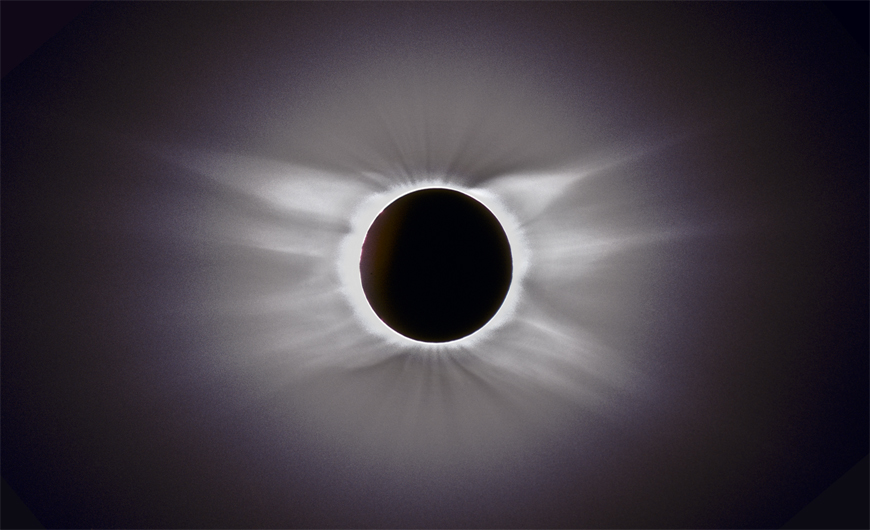
(Antarctic
@ 35 kft., 2003)! |
(Turkey,
2006)!
|
|||||||||||||
DOWNLOAD THE LATEST
VERSION OF UMBRAPHILE
VERSION
UMBRAPHILEX (RT006)
VERSION 2006B - For MacOS "Classic" Environment
CLICK
HERE for just the Data File for TSE2008 and sample camera control
parameters
(You can skip all this stuff, but fellow umbraphiles may relate to this).I am an umbraphile. Literally a "shadow lover", but properly applied, one who is addicted to the glory and majesty of total solar eclipses. Those who have basked in the moon's shadow will know what I mean without further explanation. Those who have not may have difficulty in understanding that umbraphillia is not only an addiction, but an affliction, and a way of life. The real raison d' etre for many of us. The more common and prolific term "solar eclipse chaser" is nearly synonymous, but somehow does not convey the depth of commitment to this lifelong endeavor.
Once every 16 months, or so, (on average) umbraphiles will drop whatever they are doing and trek by plain, ship, train, foot, and camel-back to gather along a narrow strip in some remote corner of the globe defined by the inexorable laws of celestial mechanics. Newtonian physics heeds no national boundaries, and neither do umbraphiles. Wherever the solar photosphere will be extincted, enshrouded by the ashen lunar disk, umbraphiles will revel in the quasi-twilight darkness. Many, including myself, will have lugged all sorts of ancillary accouterments along in an attempt to capture a bit of the magic reveled during those fleeting few seconds to review, replay, and later share with the unenlightened. Telescope, binoculars, cameras (still, movie, and video) are the non-living familiars of eclipse chasers and umbraphiles. Yet, the necessity of "working" during an eclipse demeans the moment. Every nanosecond should be enjoyed. Operating equipment detracts from the event and lessens our ability to be fully immersed in the phenomena of totality.
This was brought home to me in a series of conversations I had with a fellow umbraphile, Robert Slobins (who eclipse photos can be enjoyed in several issue of Sky and Telescope and Astronomy magazines). While returning from Banka Island, Indonesia (where I had observed my fourteenth total solar eclipse) Bob implanted the idea of using a portable computer - with a relatively intelligent and "user friendly" front-end as a camera controller. The idea was not new, I had first seen something similar implemented by George Keene, using discrete electronics, in the late 1960's/early 1970's. But the concept was evolving in my head to design something that ANY eclipse chaser could easily use, even those who normally shy away from building hardware or writing software.
As a result, ROSE was born. ROSE was the "Reprogrammable Observer for Solar Eclipses". ROSE was a prototype and fell far short of the ultimate vision. For those who are interested ROSE was built around a Rockwell AIM-65 single board computer utilizing a 1-MHz 8-bit 6502 processor (the same which powered the now dust-collecting Apple II's of the world's closets), with 4K of on-board RAM and a 20-character alpha-numeric LED display. I think you can now find one somewhere in the basement of the Smithsonian. (I had previously used them in instrument controllers and data acquisition systems I had built for a variety of ground based astronomical instruments and space mission ground support equipment, so it made a logical platform for a starting point). ROSE required entering observation/exposure "sequence tables", either from the keyboard or "downloaded" from a pre-recorded data-tape on an audio tape recorder through a TTY interface at 300-baud. (For those of you who are under 20, I'm not making this up, this really is the way we used to do things).
Before leaving for the 1991 eclipse in Mexico I had computed circumstance for several dozen potential observing sites in Baja on a "real" computer, formatted these as needed by ROSE, and transferred them to the flip side of an audio cassette which contained the Beatles "Here Comes the Sun". I had hoped to end up at one of these sites and just plug in the sequence table (which contained U.T of exposure, and exposure time). I ended up, of course, banging in a new table by hand, from a previously unconsidered (but wonderful) site.
ROSE was packaged in an old Sampsonite attaché case, with sealed lead acid batteries, interface boards, and a series of ugly toggle switches and J-connectors on the sides. It was bungy corded closed, as the case latches were broken. To this day I'm amazed and amused that on my way to Mexico airport security at LAX passed ROSE through the X-Ray inspection with no questions asked while the woman behind me with a Compaq 386 portable was asked to turn it on and boot it up. The bottom line, however, is that as controller ROSE worked superbly. It permitted me to kick back in the Mexican sand and enjoy the July 11, 1991 eclipse from the east coast of Baja California for an uninterrupted 6 minute and 54 seconds and WATCH the longest eclipse for the remainder of my lifetime and still come with beautiful pictures of the event. The only unanticipated problem I had was overheating of the CPU in the 110-degree F dessert sand. A local resident kindly lent me an electric fan and a place to plug in a 250-foot extension cord (which I just happened to carry in my "contingency" package), to keep the CPU from flipping out.
Primed by ROSE's success I was ready to metamorphisize it into something that OTHER people could use, and thus was the genesis of UMBRAPHILE. The development of UMBRAPHILE, however, laid dormant for a while. The total eclipse of June, 1992 was visible from land, only at sunrise from the East coast of Uruguay and small portions of southern Brazil. The weather prospects, with the sun hanging on the horizon, were awful. For this reason I had elected to observe this eclipse by air and had the opportunity and good fortune to navigate a DC-10 into the path of totality for 6 minutes and 15 seconds. This tied up my PowerBook (a 170 at the time), as I had to develop special S/W for this job (but that's another story). For me this was primarily a visual event. The ECLIPSE FLIGHT S/W, designed to optimize the intercept profile of such a flight by providing closed-loop control to a aircraft's navigation system, may see the light of eclipsed-day once again at a future epoch (2003 over the Antarctic, anyone?).
UMBRAPHILE made it's full debut for the October, 1995 eclipse in Ghanoli, India (near Fatipur Sekri, but just north of dynamical centerline). ROSE would not have recognized it. UMBRAPHILE was mean, clean, eclipse machine. A stand-alone program running on a Macintosh PowerBook 520c. To run one or more cameras with an optimized exposure sequence all that was required was plugging a small black box into the AppleTalk port on one side, and camera electro-mechanical interface on the other, entering in the site coordinates and waiting for the moon's shadow. UMBRAPHILE has since been "packaged" with a user-friendly, simple, GUI interface. Both 68K and PowerPC version are available (sorry, no "fat" binaries - I don't believe in taking up space on other people's machines with non- executable code). You can have it, free, it's yours to try and use. If you have suggestions, comments, or criticisms, I'll be more than happy to listen. We've got more than enough time before the 2001 eclipse to make worthwhile changes to UMBRAPHILE.
First, UMBRAPHILE computes circumstances for solar eclipses based upon polynomial representations of Besselian elements and ancillary data read in from a FITS-like header file through a standard Macintosh file requester dialog. These data are in the form which are published in the USNO Astronomical Almanac, and NASA's Reference Publications on Solar Eclipses (Espenak) . The latter of these is now available electronically through Fred Espenak's incomparable and invaluable eclipse web server. A sample file, USNO style, is distributed with the UMBRAPHILE software. This INPUT file must be a plain vanilla ASCII TEXT file (eg., you can create it, using SimpleText, or your favorite word or text processor, but don't expect UMBRAPHILE to read PostScript or PDF). Here is what the content of the first part of an UMBRAPHILE input file look's like:
; UMBRAPHILE DATA FILE FOR 29 MARCH 2006 TOTAL SOLAR ECLIPSE0. Starting up UMBRAPHILE
Just double click the UMBRAPHILE icon.
You can compute the centerline circumstances for any total or annular solar eclipse over a specified time period at a specified interval. To do this select "CENTERLINE" from the UMBRAPHILE menu. You'll see a very simple dialog asking you to enter the start time, end time and increment for the tabulation of centerline circumstances. If you had not previously read in an UMBRAPHILE input data file you will be asked to do so at this point. To read in a data file, just check the Read Data File option, and a standard file requester dialog will be presented. Then locate and open an UMBRAPHILE input data file, such as ECLIPSE-29MARCH2006_UPDATE.txt, which is currently distributed with the software. If you want to read in a new data file (having previously read in a different one) , leave this box checked. If you are re-running a new set of circumstances for a different time frame, you don't have to re-read the data file and can deselect that option.
Try this, first using the default values in the dialog. When asked, point to a sample input data file distributed with UMBRAPHILE. A new scrollable window will pop up titled "Centerline Circumstance", which will be similar in format (though the values will be different for other times and eclipses) to that shown below. Of course, you can change the start, stop, and time increment criteria as you please.

The first line in the window echoes back the name of the input file. The columns are defined as follows:
HH MM SS.f indicates the Universal Time corresponding to the tabulated values of
           the associated circumstances.  Note: UMBRAPHILE assumes that the
           polynomial coefficients supplied through the input file are
           for series representations in Universal Time (i.e., a delta-T
           correction has already been applied to Terrestrial Dynamical Time [TDT],
           Ephemeris Time [ET], or International Atomic Time [IAT]).  Both the
           USNO and NASA provide data in this form.

LONGITUDE  Give the topocentric location of the center of the moon's shadow
LATITUDE   for the corresponding instant of Universal Time.  These coordinates
           are based on a geocentric reference frame defined by the 1927 NAD.
           If a different reference datum is desired than subsequent transformations
           must be applied when high precision is required.  Please note this
           if transferring these data to maps produced outside of the U.S. on
           scales, typically, smaller than 25,000:1.  These coordinates are for
           Mean Sea Level.  Corrections for elevations above (or below) MSL
           are applied when computing local circumstances for individual sites.
           Geographic coordinates are tabulated in both decimal form and as
           degrees, minutes and seconds.  Note: Longitudes East of the
           Greenwich Meridian are positive.

DUR s      Gives the duration of totality, in seconds.  Note:  The duration is
           defined by a "smooth" lunar limb.  Corrections are not applied
           due to the selenographic structure of the moon's limb for the
           topocentic libration.  Such corrections can be on the order of seconds.
           This is discussed further in the section of this document describing
           the UMBRAPHILE Camera Controller with regard to the "diamond ring"
           sequence of exposures.

W km       Gives the width of the projected shadow ellipse, in kilometers

ALTd       Gives the altitude of the sun above the local horizon, in degrees

ECCENT     Gives the eccentricity of the projected shadow ellipse

t          Indicates the "type" of eclipse; T = total, A = annular
2. Centerline Contacts
You can also compute the contact times for locations on the centerline of the path of totality as a function of the instant of maximum eclipse. To do this select "Centerline Contacts" from the UMBRAPHILE menu, and put in the starting and ending time, and increment desired in HHMMSS.f format. You will also have an option to select (or reselect) in UMBRAPHILE input data file. When you click OK, a new CENTERLINE CIRCUMSTANCES window will pop-up similar to the one shown below:

The Centerline Contacts window, like the Centerline Circumstances window is scrollable. The Universal Times of all contacts (and time of mid-eclipse) along with their corresponding solar altitudes (ALT.) above the horizon and the position angle ( P.A.) of contacts (measured eastward from north), both in degrees, are tabulated as a function of the time of maximum eclipse along centerline. (Note: The UT of mid-eclipse is not necessarily the UT of maximum eclipse, though they usually are the same (or very nearly so) except near the points of sunrise and sunset).
To compute the specific circumstances of the eclipse for a particular geographic location, select LOCAL CIRCUMSTANCES, from the UMBRAPHILE menu. A LOCAL CIRCUMSTANCES input dialog dialog will be presented asking you to enter the latitude, longitude, and altitude (in meters) of the site of interest. Use the format shown in the dialog (just replace the values in the corresponding boxes). Note that UMBRAPHILE uses the topocentric convention where longitude East of the Greenwich meridian are positive. The name you supply, for reference, will be used in the local circumstances output window. When computing Local Circumstances you may, optionally, apply limb profile corrections for second and third contact. If you wish to do this, the values of CIIOFF and CIIIOFF in the UMBRAPHILE data file will be applied if you check "Apply Limb Corrections" (see DIAMOND RING/CONTACT II+III PARAMETERS for more information).
You can elect to apply corrections in the computation of local circumstances due to the effects of atmospheric refraction via the Local Circumstances dialog. Such effects are essentially negligible for solar elevations in excess of about 10°. It must be noted that a canonical atmospheric scale height/refractive index model with a zero-point of 20° C and 1070 mb at sea level is used. Temperature/pressure profiles of the atmosphere along the line-of-site to the Sun can vary significantly from this and affect the fidelity of these corrections - particularly at very low solar elevations. Click HERE for more information on atmospheric refraction corrections.
If you had not previously read in an UMBRAPHILE input data file you will be asked to do so now. If you wish to read a new input data file, or re-read the one you used previously check the "Read Data file" box. If you leave the box unchecked, and have read in the values from an input data file previously, they will be used again. When you click OK, after pointing to an UMBRAPHILE input data file if needed, a new output window, whose name is that of the site, will pop up giving you the local circumstances of the eclipse for the site specified. Note that the central instant of mid-eclipse (if in the path of totality/annularity) will be reported as either "MID" or "MAX" depending upon whether limb corrections have been applied.
The latitude, longitude, and altitude of the site, provided in the LOCAL CIRCUMSTANCES input dialog, will be echoed back. The durations of the penumbral phase (first contact to last contact), and the umbral phase (second contact to third contact) of the eclipse is given in hours, minutes, and seconds. These durations, and those tabulated for the centerline circumstances, assume a smooth lunar limb. The Maximum Magnitude is one of several ways to express how much of the Sun's disk is covered when the eclipse is maximum for a particular topocentric location. This is defined succinctly by J. Meeuse in his "Cannon of Solar Eclipses" as follows: The Maximum Magnitude of the eclipse, M, "is measured along the line joining the centers of the two disks. In all cases, M is the ratio of two quantities. In the numerator of the fraction, one finds the value of the straight line segment passing through the centers of the two disks and having the Sun's limb that is nearest the Moon's center, and the Moon's limb that is nearest to the Sun's center, at its endpoints. In the denominator appears the value of the diameter of the Sun". Note that this is NOT the same metric as the "Ratio of Semi-diameters", or the "Obscuration" (by area), and should not be confused with either which are sometimes used elsewhere. For each contact which is visible from that site the Universal Time of the contact, and the altitude of the sun at the time of that contact and the position angle of contact (eastward from north), both in degrees, are tabulated.
4. Circumstances for Local Noon
The local circumstances of the eclipse for the location on the Earth where mid-eclipse occurs at local noon may be computed by using the LOCAL NOON item in the UMBRAPHILE menu. This will usually be very close to (but not exactly) the point of maximum eclipse. When you select this, the geographic coordinates of that site will be determined and entered into the Local circumstances dialog which will be displayed. Then click OK (adjusting the altitude above MSL if desired), and the information described in the previous section (Local Circumstance) will be displayed. Note: For eclipses in the polar regions, this point may actually correspond to local midnight, if the moon's shadow is projected onto the Earth "over" the pole. There is not a separate menu item for this, but "local noon" actually has this meaning in that context.
System S/W: UMBRAPHILE
"Classic" (most recent version 2006B) will
run on ANY pre-INTEL CPU computer running a
Macintosh
operating system of version 6.0.X through 10.4.11, though I'm only
supporting
System 7 and later. It has been tested natively up through MacOS 9.2.2,
and in automatically involved "classic emulation" mode up through MAcOS
X 10.4.11 on a
variety of platforms.
If anyone discovers any as-of-yet unknown problems under older Mac OS
releases I will try to address them as time permits. UMBRAPHILE
will run non-Macintosh-like machines (i.e. non 68K or 60x PPC
processors) running MAE (such as a Sun SparcStation),
though your on your own on figuring out the serial hardware
interface.
UMBRAPHILEX will run on MacOS X Intel computers (not yet tested with
Leopard).
System H/W: UMBRAPHILE does
not need much horsepower to run. In fact,
it
runs happily on the original first generation series 100 Powerbooks. If
you
don't have a PowerBook, and want to revel in hands-free
eclipse-watching rather
than being a slave to your camera(s), you might consider purchasing an
older
PowerBook on the secondary market. Apple made lots of these, and
there
are many used/surplus vendors who have them going in and out of their
inventory.
My personal favorite for this purpose is the Model 170.
UMBRAPHILE
itself needs less than a megabyte of free memory to run, so even if you
have
an minimal machine with 4 Mb of RAM you should do fine. That's
running too slim for all the newer MacOS's, but manageable with a
trimmed
MaOS
7.x. A used machine in good condition with 8 Mb of RAM, 80
Mb
hard drive, battery, and a modem (typically 14,4 kbps for that vintage
-
not required but many have them) shouldn't cost no more than about
$100, probably less (finding a good battery for a machine of that old a
vintage may be more difficult than a machine itself). Though not an
endorsement, you
might
want to check the Powerbook 100 series listings with eBay,
I have found some good deals there myself; but an more recent (but
older) iBook might be a good bet.
What
About MacOS X?
A MacOS X "native" version of
UMBRAPHILE is now available. Click HERE
for information and to download UMBRAPHILEX. For older machines,
UMBRAPHILE 2006B PPC runs with no (known)
problems in "classic" mode (MacOS 9 emulation) on pre-INTEL MacOS X
machines ("classic" mode is no longer supported by Apple on INTEL based
Macs). You don't need to boot into Classic on an otherwise OS
X machine, Umbraphile will start up the classic emulator. As to
the future, well... UMBRAPHILE
was designed and written in MicroAPL's
APL.68000, and then APL.68000 Level II for the Macintosh (68K) and
Power PC (PPC) machines.
UMBRAPHILE was designed to allow a H/W control interface
through
a Macintosh serial (Appletalk; RS-422) port. In this approach, the
serial
port is dedicated to "talking to" a single device, i.e., an UMBRAPHILE
camera interface. The Universal
Serial
Buss, has replaced the Appletalk serial port(s) in contemporary
machines. USB is designed to communicate with multiple devices
simultaneously, and
hence
is an interface paradigm shift. UMBRAPHILE will work fine
as
a controller on USB equipped MacOS (such as the PowerBook G4
{Titanium})
by using a USB-to-SERIAL adapter; a small plug-in device that connects
to a USB port. Such adapters are available
from
a number of vendors, and I have found the "twin" unit from Keyspan to provide a
seamless interface. With such an adapter, select "Serial port #1"
(it has been reported that selecting serial port 2, on some G4
machines, will cause the program to hang up). In principle,
UMBRAPHILE
could be made to
work directly through the USB port. In practice, I simply have
not had
the time to do any experimenting along these lines, nor do I expect to
in the near future. I therefore beg your
indulgence
in this regard. If any UMBRAPHILE users wish to
experiment with
USB computability and find an expedient route to make this work PLEASE
let me know so I can pass it along!
What
About the Dark Side
(er, PC's)?
Sorry, but I don't do Windoze. As many know I had said previously that
"I am NOT plan on porting UMBRAPHILE to PC type
machines". However, the source code if freely available (see
Download section), and if someone were to tackle this I would be more
than pleased to see a port for those who
don't "Think Different". If anyone is seriously interested in
this (i.e.,
taking on the challenge), please contact me.". Separately, the
good
folks
at microAPL may just be about to remedy this for those who still hold
onto
Gatesian operating systems, as APLX is now
released as true Cross-Platform environment. Time will tell on
this one too, but if someone want to try it out, let me know.
; CAMERA CONTROLLER PARAMETERSThe first (camera controller) and third (diamond ring/ccontact II+III) sections are discussed first. When building an exposure sequence table, UMBRAPHILE will define a series of NUMEXP/2 - DRNUM uniformly spaced exposures from Contact 2 to mid-eclipse. Exposure times will be logarithmically ramped from the minimum exposure time to the maximum exposure time, such that each successive exposure is longer by a constant multiplicative factor (the logarithmic base) then the previous one. The sequence is repeated in reverse order from mid-eclipse to third contact.
NUMEXP = 36 ; Number of Exposures (*MUST* be even)
MAXEXP = 1.0 ; Maximum Exposure Time (seconds)
MINEXP = 0.130 ; Minimum Exposure Time (seconds)
ALARM = 20 ; Time For Audio Alarm Before CII (seconds; min = 10)
MAXDCYC = 100 ; Maximum Solenoid Duty Cycle - Warn if exceeded
; Note: Set MAXDCYC = 100 to always supress warning
;
; ELECTRONIC CAMERA SETUP AND CALIBRATION PARAMETERS (eg. Pentaz ZX-50)
ZEROEXP = 0.01 ; Send an exposure 1s before first to initialize camera shutter
PREPULSE = 0.00 ; Send "prepulse" for exposures < this time in seconds
MINRESP = 0.015 ; Minimum Response Time
MINCMD = 0.053 ; Minimum Reliable Command Time
CAMERCAL = -119.09, 1.0062, 0.00065224, -0.000000545 ; Camera calibration curve
;
; DIAMOND RING/CONTACT II+III PARAMETERS
CIIOFF = -1.3 ; Contact II offset from smooth dynamical limb
CIIIOFF = +0.1 ; Contact III offset from smooth dynamical limb
DRNUM = 3 ; Number of CII and CIII Diamond Ring Exposures
DREXP = 0.01 ; Duration (seconds) for Diamond Ring Exposures
DRSEQII = -6, -4, -2 ; Delta-Times for DREXP Relative to CII
DRSEQIII = 6, 4, 2 ; Delta-Times for DREXP Relative to CIII
You can freely edit the numerical fields of the input file
to suit your needs. Some explanation of each of these parameters is in
order.
NUMEXP  specifies the total number of exposures to take during the eclipse,
        For those of us dinosaurs still using film (which still has some
        advantages over digital imaging for eclipse photography), I can't imagine
        that anyone would really use a 24 exposure roll of film,
        but you never know. I usually take one exposure at the start of a roll
        of a "gray card" with my name and address on it, since I can reliably load
        my camera to take 37 exposures.  You can certainly specify more than 36
        exposures, if for example, you are using a large 35 mm film magazine back.
        However, you can set up for more exposures if you are using a digital camera.
MINEXP  specifies the shortest exposure time to be used, which will be for the first
        exposure immediately following the contact II diamond ring sequence, and
        also for the last exposure immediately before the third contact diamond ring
        sequence.
MAXEXP  specifies the longest exposure to be used.  The longest exposures are taken
        just prior to, and just after, the instant of mid-eclipse.

ALARM   an audio alarm is issued prior to second contact.  Set the value of alarm
        to the number of seconds before CII that you want the alarm to go off.

MAXDCYC If you are using a linear solenoid (actuator) to mechanically operate
        a shutter, to forewarn of possible over-heating, UMBRAPHILE will optionally check the
        exposure sequence table to see if the time-averged duty-cycle usage
        (activation) of the solenoid it is driving will exceed a user specified limit.
        For those using a fully electronic interface, or if this is not of concern
        in your implementation, set the value of MAXDCYC to 100.
CIIOFF  allows you to specify an offset (or correction) to the computed time of
        second contact, and thereby shift the Universal Times of ALL of the exposures
        in the exposure sequence control table.  You may wish to do this, for example,
        if the lunar limb profile for your site indicates that the center of figure is
        not coincident with the dynamical center of mass of the moon.  Such a
        correction is usually not more than a few seconds, and is provided in sources
        such as the NASA reference publications on solar eclipses (Espanak and Anderson,
        available through the Internet).  This may also be used to compensate for early
        or delayed termination of the diamond ring due to limb effects (also available
        from the same references).  This correction, and CIIIOFF for third contact,
        may be applied when computing local circumstances through the
        Local Circumstances dialog.
CIIIOFF Same as CIIOFF (above) but for third contact.  When an exposure sequence
        table is built, CIIOFF and CIIIOFF will be applied to the computed
        contact times (in the absence of limb effects) if this option is
        selected in the Local Circumstances dialog.
DRNUM   indicates how many exposures to take of the second and third contact diamond
        rings. UMBRAPHILE will compute the instant of second and third contacts for
        a smooth lunar limb. You will probably want to take a few exposures before and
        after these instants, respectively.
DREXP   indicates the duration (in seconds) of the diamond ring exposures. The example
        above is for 1/100 the second exposures, which I find very good for ISO 25
        film with an f/10 optical system. If you set this faster than the response
        time of the solenoid used to activate your camera shutter no pictures will be
        taken, so some experimentation will be needed for your particular setup
        (see the section on the hardware interface).
DRSEQII and DRSEQIII indicates when, relative to the instants of second and thirdIn the above example a total of 6 diamond ring exposures (3 prior to CII, and 3 after CIII) of 1/100th second duration will be taken at two second intervals starting 6 seconds before second contact, andsimilarly after third contact. with the spacings indicated. This will leave 30 exposures (NUMEXP - 2*DREXP) to be taken during totality. UMBRAPHILE will determine the duration of totality (or annularity) for the site specified, and will then set up (NUMEXP - 2*DREXP) Universal Times of exposures to be taken during that time in an "exposure sequence table". The first exposure following the second contact diamond ring sequence will be taken at the instant of second contact with a duration of MINEXP. A series of (NUMEXP - 2*DREXP) successive exposures increasing in duration, logarithmically, to NUMEXP - 2*DREXP just prior to mid-eclipse will be taken. This half of the exposure sequence will then repeat in reverse order to third contact. After third contact, the remaining DREXP exposures specified in DRSEQIII will be taken.
contacts, respectively, the diamond ring exposures should be taken
(time offsets in seconds). The number of entries here must match DREXP and
must be separated by commas.
The complete exposure sequence is temporally symmetric about the instant of mid-eclipse. No exposure is actually taken at the instant of mid-eclipse. The two, longest, exposures (numbers 18 and 19 for NUMEXP = 36), straddle the instant of mid-eclipse. The Universal Times in the exposure sequence table refer to the start time of the exposure, not the mid- point of an exposure.
Note: UMBRAPHILE will
support exposure times as fast as
1/1000th second (in both MINEXP and DREXP),
but some camera's with external shutter control (either mechanical or
electronic) wont! The efficacy of
either an electro-mechanical or fully electronic shutter interface for
a particular camera to respond
to such fast control signals must, obviously, be tested. This is
discussed further later.
As an example, UMBRAPHILE computed the local circumstances for 1995 total eclipse from GHANOLI, India, using geographical coordinates entered interactively, then built the following exposure table using the parameters from the UMBRAPHILE input data file for that eclipse:
##       is the exposure number
T-cont   is the time in seconds relative to contact 2 for the first half
         of the sequence, and relative to contact 3 for the second half
         of the sequence that the exposures will be taken.
T-mid    is the time, in seconds, relative to mid-eclipse, that the
         exposures will be taken.
T+CII    is the time in seconds, relative to contact 2 that the
         exposures will be taken.
UTof EXP is the Universal Time of the Exposure (hhmmss.dd).
DURAT    is the duration of the exposure, in seconds.
1/DURAT  is the inverse of the exposure duration in seconds.
With solenoid actuation, the fastest exposure which can be taken,
reliably and repeatably,
will depend upon both your camera, and the solenoid you choose. The
latter shouldn't be the limiting factor as many low-cost fast-acting
push type DC solenoids are available which can do the job. For many
35mm cameras with mechanical or electro-mechanical shutters, the
fastest response time of the button
itself (due to hysterisis in the button mechanism) is about 1/100 of a
second.
If you try to push and release the shutter button faster than that it
probably will not respond. This may also be true for fully electronic
shutters, as the shutter button will probably still be a spring loaded
device designed for human fingers.
With electronic shutter actuation "fast" exposures may still be an issue . Some cameras will "debounce" (filter against) fast exposures. See below the discussion on the QUIRKS of electronic shutter control for a more complete discussion.
In keeping with the idea of low cost, in the past, I have
successfully used
NIKON's bottom-of the line "electronic", now obsolescent (if not
obsolete), 35mm SLR model
EM. It's not a fancy camera. It's shutter control is either a)
fully
automatic, b) one manual speed at 1/90 second, or c) has a "bulb"
setting.
It does NOT have an electronic shutter control interface. In it's time
it was not my ideal choice for normal photography, but for this purpose
it is
nearly ideal. It's not in production, but NIKON made lots of them. This
means
they are cheap on the secondary and used camera markets. You would have
to
look around a bit at camera shows, through mail-order catalogs, or
internet-based resellers, but you certainly should be able to find one.
It will probably cost around $100 with the winder depending upon
the deal you can get and it's condition. It's shutter "button" is
controllable to ~ 1/100th second, so it's fine for this application
using a linear actuator.
It's also light weight and relatively small,
which is a plus when you need to mount it, and it's attached solenoid
on
a telescope. For TSE2006 I switched to using Pentax ZX-30 and ZX-50
(film) cameras, as they provide an UMBRAPHILE-friendly electronic
shutter interface, are cheap (can find for $ 50 with a built in film
winder), and were well suited what I wanted to do (See HERE).
Now, do you have to use one of these? Of course not. I'm just passing this along in case you need to purchase a camera for this purpose and that a really fancy, pricey, new 35mm SLR or DSLR is not at all required.

ZEROEXP   (NEEDED for "Classic" MacOS UMBRAPHILE [2006 B) only.
          If the FIRST exposure of a sequence is failing to execute (shutter does not open)
          set this parameter to a non-zero value.  UMBRAPHILE will then "pulse" the shutter
          control line for the duration specified (in seconds) one second prior to sending
          the actual shutter open command.  This (for some reason) seems to pre-condition the
          shutter response.  Make the pulse short (suggested 0.01s as a first "guess").
          If it is too long an otherwise balky shutter will respond and you'll waste a picture.

PREPULSE  some cameras seem to fail intermittently for exposures shorter than some threshold
          (see MINCMD) if (and only if) exposures are spaced "too far apart".  This too
          requires experimentation, and can be investigated using the "Serial Port Test
          Mode" as an intervelometer.  For example, in the case of a Pentax ZX-50 every other
          exposure will fail if the exposure times ar < 0.053s AND are spaced more than 3
          seconds apart.  To remedy this exposures shorter than this empirically determined
          threshold can be set up to be "pre-pulsed".  I.e., just like a failing ZEROEXP, a
          very short (prepulse) command can be sent to the shutter mechanism to pre-condition
          it before an actual shutter-open command.  Setting PREPULSE to a non-zero value
          (in seconds) will do that.  Indeed it will send a pulse of a duration specified,
          which should be shorter than MINRESP (see below), 1/50th of a second before the
          actual shutter open command.  In some cameras this will then cause the "failing"
          shutter open commands to work.

DELPULSE  (NEEDED for native MacOS X (UMBRAPHILEX) only.
          Specifies the time (in seconds) between a PREPULSE and and the shutter opening.
          Set to < MINCMD (suggested ~ 10% less, but best if shortened until the point
          where robust shutter openings may otherwise fail).

MINRESP   All cameras tested so far have a MINIMUM (fastest) time that the shutter can be
          commanded open.  Below that either (a) the shutter simply won't open, or (b) the
          shutter WILL open, but not for the time specified.  For example, with a Pentax
          ZX-50, commanding any exposure shorter than 0.015 sec (about 1/67s) will result
          in a 1/67s exposure.  You can ASK for a 0.002s (1/500th sec) exposure, but the
          shutter will deliver only a 1/67s exposure.

MINCMD    this is the MINIMUM *RELIABLE* command time.  It is the time (in seconds) at and
          longer than, the shutter will ALWAYS open regardless of how long it has been since
          a previous exposure was taken.

CAMERCAL  This gets a little bit complicated...  Some camera shutters will respond (open) to
          commands for commanded exposure durations longer than MINCMD, but the duration the
          shutter will stay open is NOT what is commanded.  The relationship between the
          shutter open COMMANDED time and the shutter open RESPONSE time can be very
          non-linear.  Below is a graph of that empirically determined relation for a Pentax
          ZX-50 (by measuring the shutter open time off an oscilloscope screen).

        The above graph is shown as log-log because of the large dynamic range (factor of
        100 explored in exposure time).  What it says is:
        (a) if an exposure < 53 ms is commanded, the shutter will open for only 15ms,
            if it opens at all (in the case of the ZX-50 it must be prepulsed if the
            previous exposure was more than 2.7s earlier - as was done here)
        (b) The relationship between the COMMANDED and ACTUAL (response) shutter open
            times above this threshold is very non-linear.  Note a 100 ms (0.1s)
            shutter open command will result in only a 20ms (0.02s) exposure!  This
            disparity gets better for longer exposures, and by half a second the
            commanded and actual exposures are virtually equal.

       CAMERCAL expresses that relationship as the four coefficients of a 3rd order
       polynomial fit to the (measured) response function if Tc > MINCMD (where
       Tc is the commanded exposure time.  I.e., what you will get will be very close
       to:  Te = CAMERCAL[1] + CAMERCAL[2]*Tc + CAMERCAL[3]*Tc^2 + CAMERCAL[4]*Tc^3

       It is expected that not everybody will have calibrated this (but you SHOULD
       so you know what you will actually get from an exposure sequence), so
       UMBRAPHILE does not USE this information to build a command sequence - but it
       WILL show you what you would ACTUALLY get (or very close to that if the
       calibration was determined accurately).  with that you can TUNE your CAMERA CONTROLLER
       PARAMETERS to get the dynamic range of coverage you actually want.  This was done,
       for example, using the parameters shown in the example earlier on this page
       (MAXEXP = 1.0, MINEXP = 0.13).  With that, played through the Camera Calibration
       curve, the expected ACTUAL exposures are shown as the last column in the exposure
       table which is built.  For example:

Setting these parameters requires some experimenting,
but once you know what your camera actually does, the
response should be reproducible.
When an exposure is to be taken, UMBRAPHILE will transmit a series of '00'X characters, over the transmit data line. This will result in the buffer's output line going high (+5V), with a ~ 90% on-time duty cycle for as long as desired. It's not possible to assert this line high continuously, but at 9600-baud, having one bit toggle with the others high, is so rapid that the solenoid does not have time to react to the transitions. With many reed-relays you will be able to hear a 9600 Hz "squeal" when activated. This is perfectly normal, and indeed an audio indication that everything is working. The time-averaged voltage applied to the relay will be slightly less than 5V, but the deficit is sufficiently small that the relay will toggle without any problems. For those who are concerned, or are getting marginal performance, you could filter or "pulse shape" the output of the 7404 to the filter, but I've found this really isn't needed.
The linear solenoid is powered by a 12 Volt battery. I have chosen to use a 12VDC 1.2 Amp- Hour sealed lead acid cell. These are very common, small packages. New they sell for ~$20.00 from chain outlets like "Batteries Plus", but are readily available from parts resellers and surplus houses for ~ $10.00. These, of course, are rechargeable over many hundreds of cycles and are a much better value than dry cells. If you are using a 24 Volt solenoid, just use two of these in series.
I have chosen to power the TTL package and reed-relay with a separate 9VDC "transistor battery" through a 5VDC voltage regulator (click here for that schematic). There is no reason that one could not also power this using the 12V battery used for the solenoid (as shown in the above schematic). The reason I use a separate battery is to easily avoid any transient signals which could arise from switching on the solenoid, which (depending upon the specific unit) could have a relatively high in-rush current. Yes, one could filter against this, but simplicity said just use a separate battery.
Packaging and Cabling: The whole electrical interface unit fits into a small hand-held "control" box (about the size of a 36-exposure 35mm slide box). The circuit described above, and the 9V battery fit into the box. Mounted on the box are two miniature SPST toggle switches, a female RS- 232 jack, and a two conductor miniature plug to supply the 12V DC power from an external battery. You certainly could use a larger box and house the 12V battery inside to eliminate one cable and jack/plug connection.
I have used two separate switches for each battery supply. A unit
on/off switch for the gate/relay and a separate solenoid arm/disarm
switch. This probably isn't necessary, but it will force you to both
turn on and enable computer control. This will prevent an "operator
error" from accidentally using up film is a mistake is made.
|
S ee the accompanying Parts
List and Above Discussion
 |
Parts (of course you can substitute) * Optional, for separate logic supply (not regulated from +12V solenoid power).Nearly all of these parts, except perhaps the solenoid itself, can be purchased from parts retailers like Radio Shack, or you can mail-order from any number of wholesalers. Of course you can substitute or customize. This is intended just to give you an idea of one implementation. As far as a solenoid is concerned I have that one of the following two, both manufactured by LEDEX, will work well with most cameras: LEDEX # 81840, 12 to 24VDC Small Push-Type Solenoid,These specific models have been replaced (but are still available on the secondary market), and others certainly canbe used. I strongly suggest that you obtain a few of different varieties, and determine which works best for your camera. You may want to consider going directly to Ledex and buying a new one. Model numbers 3315 and 3325 look particularly promising and applicable for this purpose. (Find out what they have in stock as you probably can use one of several flavors, as the cost set-up for a production run is prohibitive). If you do use a 24-Volt solenoid, use two lead-acid batteries in series, or a 24-Volt one (if you can find one), and be sure to use a voltage regulator which is designed for 24V input and 5-Volt output. This should be no problem as most regulators work in the range of 12-24, or 12-35 Volts. Actually, if you have a 12-Volt solenoid, you may want to try it a 24-Volts (2x over-voltage), as you can get more force out of it. As long as you are not energizing it continuously over-heating will probably not be a problem. While this is not a formal endorsement, I have found a good source for parts, including solenoids, is C&H Surplus, 2176 East Colorado Blvd., Pasadena, CA 91170 (telephone: 626-796-2628). Their prices are very reasonable, and while their stock changes over time they also carry batteries and other parts so you could probably get everything except an AppleTalk connect there. (If you are a tinkerer at heart, and are lucky enough to live near Pasadena, this is a NEAT store to walk around in. Looks like a giant incarnation of my basement {when I had one!}). |
If you want to use this on a camera tripod (rather than a telescope), then you will want to affix a 1/4-20 nut (either with a flange, or soldered/welded or epoxied on - depending upon materials used -but affixed in some form) to the bottom of the frame.
Note: Linear actuators which do not captivate the central plunger cannot be used in a horizontal configuration (as the plunger can be pushed out of its collar when returned after actuation). This can be a problem if you are photographing the eclipse at a small zenith distance. In that case you will need a "right angle" system to mount your camera (as naturally occurs on a Newtonian telescope, or a right-angle prism on a Schmidt-Cassegrain). Just thought I should mention this, though you would obviously discover this yourself the first time you tried this with such an actuator in a horizontal orientation - when the plunge comes flying out of the collar if not captivated.

1. Assigning/Specifying the Serial Port.
The UMBRAPHILE camera controller software "talks" to your camera through a built-in physical (or USB emulated) serial port in your MacOS computer. Since the camera controller is designed as for field operations, most users will be running UMBRAPHILE on a Macintosh Powerbook or iBook.
(Have a newer Mac laptop without a serial port? Use a
USB-to-serial converter; see above)
FOR MacOS "Classic" ONLY:
While, historically, older Powerbooks had only one built-in serial port, the default port designation apparently changed with the advent of the G3 Powerbooks. With pre-G3 Powerbooks (eg., 100, 500, 5000 series), the built-in serial port was port #1, aka the "Modem port". With the G3 series this, by default, seems to have changed to port #2, the "Printer" port. Of course, desktop Macintoshes (and clones) have two built-in serial ports. The first thing you must do when you select RUN CONTROLLER is tell UMBRAPHILE which serial port you will be running your camera interface through. This usually is Port 1. However, if you are running a G3 it may be Port 2 - but then again it may not be, as this depends upon how your system is configured. If you are not sure, just try one, if it does not work, the other will! You must also check that the selected port is NOT already in use by another application, or by AppleTalk. UMBRAPHILE will reprogram the communication parameters on the selected port, so if it is in use by another application, that application is likely to get "confused" and a conflict situation can arise. The RUN CONTROLLER menu item will pop up the following dialog:

If you are unsure of the status of the selected serial port, click WAIT! - Let Me Check, and verify the port is not in use. Note that if your computer has an Ethernet or IRDA port, you do not need to disable AppleTalk. Just make sure that AppleTalk is not active on the port you selected.
Note: For G4 desktop
machines, port 1 should be selected, or the S/W might hang-up.
FOR MacOS X ONLY:
To
identify to UMBRAPHILEX the port name assigned by a USB-to-Serial port
adapter plugged into your Mac use the SET USB PORT menu item.
Read item number 1 discussed HERE.
2. Changing the Serial Port Communication Parameters.
(You probably won't need to do this, but...)
FOR MacOS "Classic" ONLY:
If you click OK - I'm Sure, Go Ahead., in the above dialog, you will then be presented with a second dialog which is used to reprogram the communication parameters on the selected serial port. By default, and appropriate for use of the electro-mechanical shutter activated solenoid described later on, UMBRAPHILE will set the port parameters as follows:
Baud Rate = 9600 BPI
Duplex = HALF
Character Translation Mode = ASCII
Parity = NONE
Stop Bits = 1
Data Bits = 8
Hand Shake = None
Control Character = '00'X
If you are using the UMBRAPHILE interface described in this document then you probably don't need to know this, and just click OK, Do it. If, however, you are using UMBRAPHILE through an interface circuit designed to control a fully electronic shutter activation mechanism with a camera that has a recalcitrant shutter, you may need to present a different signal to your interface circuit. If that is not the case, skip this... You can do this by changing the port communication parameters in this dialog:

UMBRAPHILE will then ask you to click OK (in a
confirmatory dialog) when you are ready to reprogram the port. If
UMBRAPHILE
is unable to access the selected port, for example if you specified
port
1 (the Modem port) on a G3 laptop configured to designate "port 2" as
the
ID for the serial port, you will be so advised and asked to select the
other port.
FOR MacOS X ONLY:
To verify the status, or to if needed, redefine the operating
parameters of your USB-to-Serial port adapter, use the unix stty command in a Terminal
window. See item dumber 2 discussed HERE.
Building the Exposure Sequence Table
2. Enter the Latitude, Longitude, Altitude (in meters) of the site, and provide a site name, through the LOCAL CIRCUMSTANCES dialog, which will automatically pop up. If you previously entered this information by running the eclipse calculator, just click OK. If you check the box which says READ DATA FILE, a file requester dialog will be presented asking you to point to the UMBRAPHILE data input file (such as ECLIPSE-21JUN2000_231.DATA, which is distributed with the UMBRAPHILE software). If you previously read in the input file you want to use you can deselect this, so you won't have to read it again.
3. UMBRAPHILE will the compute and display local circumstances for the site in a new pop-up LOCAL CIRCUMSTANCES window.
4. UMBRAPHILE will build the exposure table described above,
and, optionally, check the
duty-cycle utilization of the camera
controller solenoid. If you are using an electronic shutter
interface, and have set MAXDYCY = 100 in the UMBRAPHILE parameter file,
you won't see this.
Note for users of electro-mechanical shutters: Most push-type solenoids are not designed for continuous activation, particularly if used in an "over-voltage" condition. If the time- averaged duty cycle exceeds 6% UMBRAPHILE will present an informational message/warning such as:

If you are a solenoid user, don't let this scare you. First, it is of no relevance if you are using an electrical shutter interface - and you can supress this by setting MAXDCYC = 100 in the input data file, and skip to the next section. But if you have built a solenoid hardware interface with a really cheesy, cheap, low-voltage solenoid, have not heat-sinked it in any way, and are running it at 4-times overvoltage, it will probably fail to work with about a 6% duty cycle halfway through the exposure sequence. (The value of 6% was chosen empirically by testing several different solenoids, but may be very different {more robust} for specific units). What happens is simple, it gets hot. When it gets too hot it can no longer produce the force needed to push down the shutter. Or, it could stick in the "down" position even when not energized, as the "plunger" thermally expands in it's collar, holding the shutter opened. Any reasonable solenoid run at even 2-times overvoltage should have no problem with a 25-50% duty cycle for several minutes. Presumably you will not be doing this for the first time during the eclipse (practice makes perfect), and you should have a good feeling about at what level your particular system will not perform as expected. If you do get the warning, and your happy with it just click OK - Run Controller Anyway. If not, and it's too late to change the hardware there are two things you can do:
1 - Decrease the maximum exposure time. You will loose someIf you've built and "tuned" the interface before the eclipse this situation should not arise. Where can you get a good linear actuator (tubular solenoid)? See the notes in the Parts List section. Whew! enough about that.
outer corona so you may need to compensate with faster film.
2 - Decrease the number of exposures.
The threshold against which the time-averaged duty-cycle of
solenoid activation in the exposure sequence table is checked is
established by the value of the MAXDCYC parameter in the
UMBRAPHILE input data file.
As distributed (and in the above example) this is set to a very
conservative 6%, but may be adjusted when you have gained some
experience (and confidence) in your hardware implementation. If
you are using a fully electronic interface this check is unnecessary,
and you can set the MAXDCYC parameter value to 100.

When you're running the UMBRAPHILE controller for real,
and click OK. When you're testing you can adjust the offset to
simulate
any U.T. you want, but you do NOT want anything but a zero-offset "in
real life"!
6. The UMBRAPHILE Timer window will pop up (assuming you clicked OK in step five). This is a real-time updating status display keeping you appraised (in BIG letters and numbers) as to where you are in temporally. The window will look something like this:

The title bar (first line above) has a continually updating U.T. clock. To the right of this is a counter which indicates which exposure is next (by number) and what it's duration is (in seconds). Below this the U.T. start time of that next exposure is shown, and to the right (updating) the delta time until that exposure. Below this three clocks are continually updating which give the time until (or since) second contact, mid-eclipse, and third contact. Three informational messages are displayed at appropriate times below this. At a preset (but > 10) number of seconds seconds before second contact an audible alarm will be sounded through the computer speaker(s) and the message FILTERS OFF, ENABLE ON will be displayed. The one thing UMBRAPHILE will not do for you is take the solar filter off of your camera, but it will try to help you to not forget to do so, and remind yoy to make sure that your camera shutter control is enabled!. Between exposures the message WAITING. While an exposure is in progress the message EXPOSING will be displayed. (In the MacOS "Classic" version of UMBRAPHILE" You will se an option to display this in monochrome, which you may want to do if your are filtering your computer screen with a red filter to preserve your dark adaption during an eclipse).
As the exposure sequence is executing, the rows (lines) in the exposure sequence table window which
have been completed will be inverted (displayed as white on black), so
the black rows of already finished exposures will "march" down the
window during the eclipse.
WATCH THE ECLIPSE!...
UMBRAPHILE will do the rest.
I. You can export the content of any of the currently
displayed output windows (Centerline,
Local Circumstances, and Exposure Sequence Table) to a text
(ASCII) file. You can do this at any time EXCEPT when you are
actually running the controller (i.e., the clocks are running in the
UMBRAPHILE
timer window). If you want to save the sequence table you are
executing you have two options:
a) INTERRUPT (Long before the Eclipse!). This will not close the sequence table window, it will just stop the controller and timer windows. You can then save the window content.
b) Wait until the execution of the exposure sequence completes, then save the window content. When you select SAVE WINDOW a dialog will pop up with the names of all of the currently open text windows. Just pick the one whose content you wish to export to a file, and a file requester dialog will be brought up to allow you to do this.II. You can also save all of the setting you have established in the various UMBRAPHILE dialogs, to be restored as is, at a later time. This will permit you to re-run a particular scenario or set of inputs, without having to enter your values, switches, selections, etc., over again. To do this select SAVE SETTINGS, and you will be asked to supply a name for your "Settings" file. You may restore those saved settings at any time by using the GET SETTINGS menu item. Note that saving the on-the-fly changeable UMBRAPHILE settings does not alter the parameter values in your input data file. Should you want to change these you will need to do so in an external text editor/word processor.
Please feel free to redistribute UMBRAPHILE to anyone who may be interested. When doing so please keep this description and these instructions with the software (for the overly litiginous - please see LEGAL Stuff).
GLENN SCHNEIDER'S: HOME PAGE or ECLIPSE CHASING INFORMATION
Or, snail-mail to:
Glenn Schneider

|
This site is owned by
Glenn Schneider |

|
| [Previous] [Skip Prev] [Skip -5] [Next] [Skip Next] [Skip +5] [Random] [List] [Join] |


