TSE 2005 IMAGING PROGRAM - HMS GAUGUIN
TSE 2005 will be observed, and imaged, from
the HMS Gauguin in the South Pacific. Line-of-sight instabilities
in camera pointings are expected due both to the motions of the ship in
response to sea and wind driven waves, and higher frequency vibrations induced
by the ship's mechanical systems. Much like TSE 2003, imaged from the flight
deck of a Boeing 747-400 ER over Antarctica, we hope to reduce the magnitude
of these effects by mounting a small suite of imaging instruments on a vibration
isolated, gyro stabilized platform. Four cameras/lenses will be used
as follows:
1) SBIG ST-2000 XM CCD imager with a 300mm lens and narrowband "green"
filter similar to the SOHO/LASCO C2 bandpass.
2) NIKON F5 35mm film camera with a Nikon 400mm f/5.6 Vibration Reduction
(refractive elements) Lens
3) PENTAX 35mm film camera with a celectron 90 1000mm f/13.2 catadioptric
lens
4) Sony CR TRV 900 NTSC, three CCD Digital Video Camera.
See http://nicmosis.as.arizona.edu:8000/ECLIPSE_WEB/ECLIPSE_03/QF2901_IMAGING/TSE2003_REPORT.html
for information germane to the optical/hardware configuration here.
All four cameras are optically co-aligned and mounted on a common platform
along with two orthogonally mounted dual-axis gyro stabilization units,
together, giving three axis stability augmentation. The gyro units,
house titanium flywheeels, spinning at 22,000 RPM on flotation bearings in
helium filled cylinders. These units are manufactured by Kenyon Laboratories
and are described here: http://www.ken-lab.com/
The platform is balanced, and detorqued from the effects of power, control
and data lines, and cooling lines, and when free suspended - literally on
a "bungie cord" - will nominally point the cameras "upward" at an angle of
60.5 degrees. Adjustable counterbalances provide appx +/- 8 degrees
of repositioning tolerance in the event the ship is moved to an alternate
position with the Sun at a different altitude in the sky. Some images
of the camer/gyro platform, before final counterbalancing, cabling,
and suspension, can be seen below:
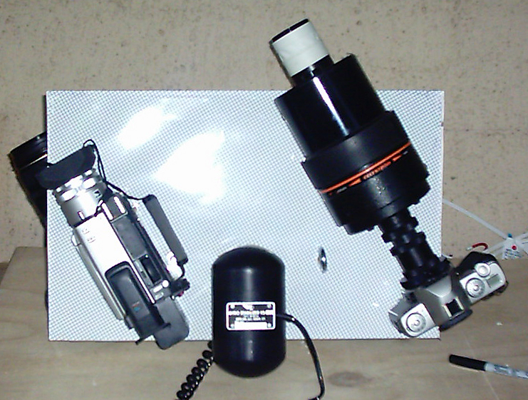
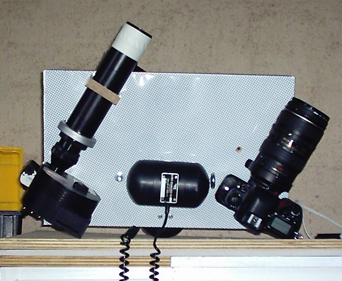
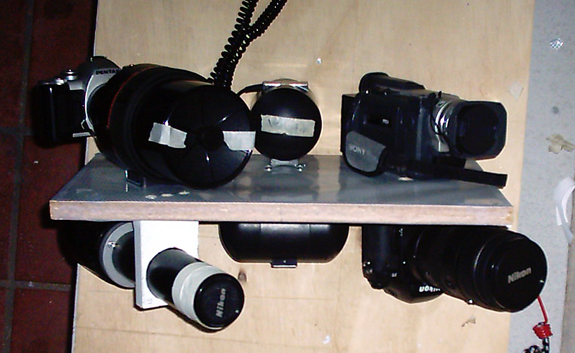
Image acquisition with the CCD imager and the two film cameras will be
fully automated with electronic control interfaces, the later two driven
by UMBRAPHILE.
Real-time video will be streamed off the platform to an external
computer for guiding an platform pointing corrections.
FILM CAMERA IMAGING SEQUENCES:
The baseline plan is predicated on:
a. A decision to use a c90 (1000mm @ f/11) on the Pentax camera and
b. A decision to capture at high cadence (and rapid shutter speeds) the
CII and CIII sequences with off-platform cameras.
In defining an UMBRAPHILE exposure time sequence for film cameras to be
autonomously operated by a single computer for TSE2005 both cameras
will execute exactly the same exposure sequence, so differences in photometric
response will be determined by film speeds and f/ratios. The two film
cameras on the gyro platform as follows have the following characteristics.
CAMERA 1 = NIKON F5 with 400 mm f/5.6 VR lens
- Minimum shutter response = 1/25th (0.04) sec.
CAMERA 2 = PENTAX with c90 1000mm f/13.2 lens - Minimum
shutter response = 1/100th (0.01) sec.
(See: notes on VR lens "keep-alive").
The exposure sequences are defined with priority to capture the mid/outer
corona with the NIKON + 400mm f/5.6 lens and the inner/mid corona with the
Pentax+1000mm f/11 lens given their relative image scales, fields of view,
and lens "speeds". A lessser "goal" is to capture SOME of the limb
phenomenon at and near CII and CIII, albeit more deeply exposed then optimally
as will be apparent. This, however, is less important in defining the exposure
sequence as those phenomenon will be captured by off-platform cameras dedicated
for that purpose with higher temporal sampling around the contact times, and
can achieve faster exposure times (see limits for the platform cameras above)
for these bright phenomena.
Note: For either camera, exposures commanded as faster than the
minimum shutter response times will execute at the minimum time.
This is a limitation in both cameras shutter control firmware.
Usage Summary:
400mm EFL @ f/5.6 for the NIKON <- wider field
outer coronal imaging
1000mm EFL @ f/13.2or the PENTAX <-smaller field inner coronal
imaging (limb and contact phenomenon)
UMBRAPHILE takes exposures UNIFORMLY SPACED IN TIME between the predicted
UTC of CII and CIII (computed based upon the ship's position). Because
of the brevity of this eclipse (appx 35s), IF no exposures on a 36
exposure roll of 35mm film are "reserved" to take any pre/post CII/CIII
images the cadence of the images would be appx 1 frame per second (both
cameras using 36 exposure rolls of film). Exposure durations are logarithmically
ramped up from a commanded minimum at CII (to a maximum at mid eclipse) and
then symmetrically back down to CIII. With this relatively rapid cadence the
contact post CII and pre CIII contact phenomenon (chromosphere, in particular)
will be well covered temporally by that sequence. To capture that at
higher spatial resolution (with the 1000mm lens and faster responding Pentax)
the fastest commandable exposure time should be used to start and end the
uniformly sampled sequence; i.e., 0.01s. This means that the CII/post-CII
and pre-CIII/CIII images taken by the F5, will all be at 0.04s, as that is
the fastest that camera can respond.
Off-platform cameras recording the limb phenomena at higher cadence and
speed, but a few frames before and after CII and CIII, respectively, will
be taken to capture respective pre/post contact phenomenon. TWO exposures
before predicted CII and TWO after predicted CIII.will be execute at -5,
-2 seconds, w.r.t. CII and +2, +5 seconds w.r.t. CIII. This will leave
32 exposures for true "totality", 16 on the ramp up, and 16 on the ramp
down with an inter-image cadence of appx 1.18s.
To consider a MAXIMUM possible exposure duration (the two frames straddling
mid-eclipse) for deepest (most sensitive) imaging, time must be allotted
for operational overheads: Film advance operations (about 0.3s), and very
conservatively for mechanism jitter damping (suggest about 0.3s). Hence
the maximum possible exposure duration is appx 0.6s, but a maximum exposure
time of 0.3s will be planned, as discussed below. It is unclear that
the pointing will be sufficiently stable for these longest duration exposures
- but we will take many shorter as we ramp up and down, and this will be
attempted.
Such a sequence, with a cadence of 1.18s between exposures, is as follows:
## T-cont T-mid T+CII HHMMSS.ff
EXPTM 1/EXPT
1 -5.00 -23.27 -5.00 195731.57
0.010 100.00
2 -2.00 -20.27 -2.00 195734.57
0.010 100.00
3 0.00 -18.27
0.00 195736.57 0.010 100.00
4 1.18 -17.09 1.18
195737.75 0.013 79.71
5 2.36 -15.91 2.36
195738.93 0.016 63.54
6 3.54 -14.73 3.54
195740.11 0.020 50.65
7 4.72 -13.56 4.72
195741.29 0.025 40.37
8 5.89 -12.38 5.89
195742.47 0.031 32.18
9 7.07 -11.20 7.07
195743.64 0.039 25.65
10 8.25 -10.02 8.25
195744.82 0.049 20.45
11 9.43 -8.84 9.43
195746.00 0.061 16.30
12 10.61 -7.66 10.61 195747.18
0.077 12.99
13 11.79 -6.48 11.79 195748.36
0.097 10.36
14 12.97 -5.30 12.97 195749.54
0.121 8.26
15 14.15 -4.13 14.15 195750.72
0.152 6.58
16 15.32 -2.95 15.32 195751.90
0.191 5.25
17 16.50 -1.77 16.50 195753.07
0.239 4.18
18 17.68 -0.59 17.68 195754.25
0.300 3.33
19 17.68 0.59 18.86
195755.43 0.300 3.33
20 16.50 1.77 20.04
195756.61 0.239 4.18
21 15.32 2.95 21.22
195757.79 0.191 5.25
22 14.15 4.13 22.40
195758.97 0.152 6.58
23 12.97 5.30 23.58
195800.15 0.121 8.26
24 11.79 6.48 24.75
195801.33 0.097 10.36
25 10.61 7.66 25.93
195802.50 0.077 12.99
26 9.43 8.84 27.11
195803.68 0.061 16.30
27 8.25 10.02 28.29
195804.86 0.049 20.45
28 7.07 11.20 29.47
195806.04 0.039 25.65
29 5.89 12.38 30.65
195807.22 0.031 32.18
30 4.72 13.56 31.83
195808.40 0.025 40.37
31 3.54 14.73 33.01
195809.58 0.020 50.65
32 2.36 15.91 34.18
195810.76 0.016 63.54
33 1.18 17.09 35.36
195811.93 0.013 79.71
34 0.00 18.27
36.54 195813.11 0.010 100.00
35 -2.00 20.27 38.54 195815.11
0.010 100.00
36 -5.00 23.27 41.54 195818.11
0.010 100.00
The exposures in blue are the predicted times of CII and CIII.
Note that exposures commanded shorter than (0.04s) 1/25 second with the
400mm+ NIKON F5 will be taken at 0.04s.
FILM SPEEDS.
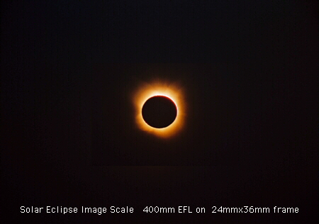
NIKON with 400mm lens. With the Sun centered and using a 400mm lens,
the long axis of the 36mm x 24mm field will extend about 8 solar radii along
above the photosphere to the edge of the field of view (along the image horizontal).
At f/5.6, a "typical" corona, on the azimuthal median, would be imaged with
an exposure time of appx 0.3s with ISO 800 film at 8 solar radii.
As the Nikon F5 cannot take an exposure shorter than 0.04s, the dynamic
exposure range with the above sequence is a factor of only 7.5 in this camera.
For the fastest, 0.04s, exposures which of course would also be then
at ISO 800 and f/5.6 we might expect to optimally capture the corona at 4
solar radii beyond the photosphere, but imaging at ~2 solar radii above photosphere
will be overexposed. This is acceptable for this "wide field" camera with
the goal of 2 < r < 8 solar radii coronal imaging.
PENTAX 1000mm f/13.2. To use this camera to push into the inner
corona at r = 0.1 solar radii above the photosphere at the shortest executable
exposure time (0.01s) suggests the use of an ISO 150 film. For typical
surface brightnesses of prominence, the brightest positions might be panchromatically
overexposed (w.r.t. an optimal exposure) by about a factor of 4, which is
tolerable. With ISO 150, at 0.3s (the longest exposure time suggested
for the 400mm lens for outer coronal imaging), we could expect well exposed
coronal imaging at appx r = 1 above the photosphere.
We have a small "gap" at equal S/N in the radial zone of appx 1 < r
< 2 solar radii. Likely, this will be either overexposed in the
400mm camera, or underexposed in the 1000mm camera - but without knowing
apriori the actual coronal brightness it is impossible to know which will
be the case. In any event, we should capture that region in one camera
or the other - and image co-addition/processing when not fully saturated
is planned. The radial domain of overlap between the two cameras does not
have to be exposed at the same photon S/N. Note that the log-ramp of
exposure times within a given camera changes by 31 % in exposure time from
exposure to exposure.
SANITY CHECK. The stability of the pointing with exposures as long
as 0.3s is a concern. The the longest exposures used for the TSE 2003
gyro stabilized platform were 0.17s. In this "experimenting" we will push
longer by a factor of about 2 - but a ship will not be as inherently as
stable as the aircraft (unless we get lucky!). For the QF2901 400mm
imagery we push processed ISO 800 film to 3200. Depending upon sea/stability
conditions we may make a decision to cut the maximum exposure time in half,
and push one stop (i.e., to ISO 1600). Indeed, the sky will likely
not be as transparent at sea level as it wa at 35,000 feet over the Antarctic
and it may be prudent in the end to push two stops. But, we should remain
flexible.
Based on experience from TSE
2002 and TSE
2003 Fuji NPZ 800 for the NIKON camera - and depending upon conditions
(stability and transparency) allow to push to ISO 1600 or 3200.
For the 1000mm f/5.6 camera ISO 150 is nominal, and various emulsions are
under consideration. We will select a film in the range of ISO
100 to 400 for the 1000mm, appropriately for how the NPZ 800 is to be pushed
(if it is) based upon the sky and platform stability conditions.